background image

- (02 - 15) -

O

U

TD

O

O

R U

N

IT

AO

G0

9-

14

LV

C

N

O

U

TD

O

O

R U

N

IT

AO

G0

9-

14

LV

C

N

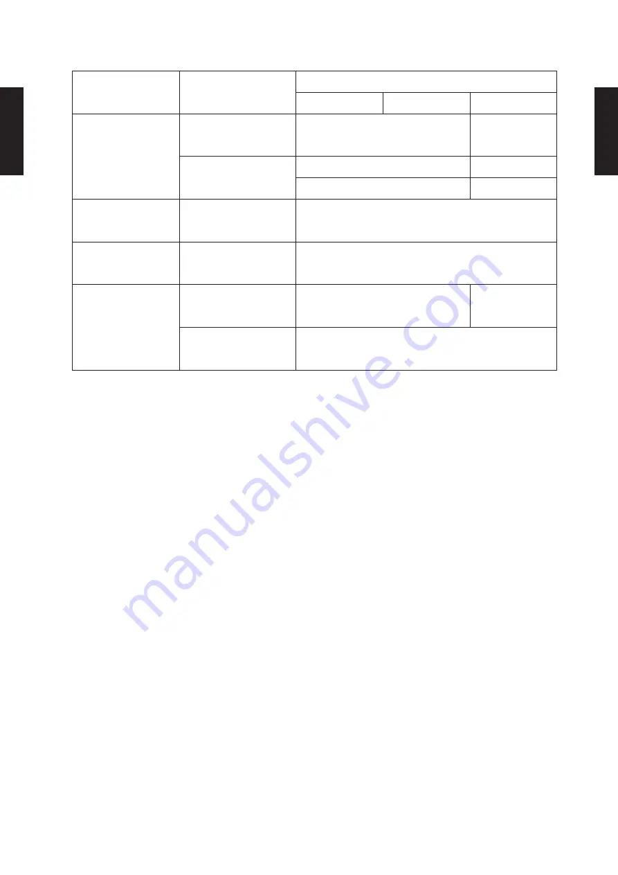
SAFETY DEVICES

10. 

Protection form

Model

AO

G09LVCN

AO

G12LVCN

AO

G14LVCN

Circuit protection

Current fuse

(NEAR THE TERMINAL)

250V 20A

250V 5A

Current fuse 

(MAIN PRINTED CIRCUIT 

BOARD)

250V 15A 

250V 5A 

250V 3.15A 

250V 3.15A 

Fan motor protection

Thermal protection 

program

OFF : 100±15°C

ON : 95±10°C

Compressor protection

Thermal protection 

program

(DISCHARGE TEMP.)

OFF : 110°C 

ON : After 7 minutes

Heater Protection

Current fuse

250V 5A (2pcs)

250V 5A(1pc)

Thermal protection switch

(Heater temp.)

OFF: 55

+3

 -3

°C

ON: 45

+4

 -4

°C

Summary of Contents for AG G09LVCB series

Page 1: ...AIR CONDITIONER Floor type INDOOR OUTDOOR AG G09LVCB AG G12LVCB AG G14LVCB AO G09LVCN AO G12LVCN AO G14LVCN DESIGN TECHNICAL MANUAL ...

Page 2: ...1 INDOOR UNIT FLOOR TYPE AG G09LVCB AG G12LVCB AG G14LVCB DTR_AG004E_03 2013 01 21 ...

Page 3: ...AN PERFORMANCE AND CAPACITY 01 12 7 1 AIR VELOCITY DISTRIBUTION 01 12 7 2 AIRFLOW 01 13 8 OPERATION NOISE SOUND PRESSURE 01 15 8 1 NOISE LEVEL CURVE 01 15 8 2 SOUND LEVEL CHECK POINT 01 17 9 ELECTRIC CHARACTERISTICS 01 18 10 SAFETY DEVICES 01 19 11 EXTERNAL INPUT OUTPUT 01 20 11 1 EXTERNAL INPUT 01 20 11 2 EXTERNAL OUTPUT 01 22 12 FUNCTION SETTINGS 01 24 12 1 INDOOR UNIT Setting by remote controll...

Page 4: ...n at 25 C outdoor air temperature Heating 25 to 24 C Specification improvement that can be operated under extreme low outdoor temperature 25 C without trouble Nordic model Freezing prevention of bace Structural improvements Expansion of mechanical space Improvement of cold proof specifications of parts Standard model Nordic model Heater less Base 0 C 3 C OFF ON Heater operation Outdoor temperature...

Page 5: ... 9 5 7 5 2 4 0 4 2 4 0 3 5 Heating capacity kW Heating capacity kW Heating capacity kW 09 Class Outdoor temperature 15 C 7 C 2 C Outdoor temperature 15 C 7 C 2 C Outdoor temperature 15 C 7 C 2 C 12 Class 14 Class Up and down twin fan operation z z Up to every corner of the room especially around the feet is heated evenly by two direction up and down discharge Cooling Heating ...

Page 6: ...e Piping 1 6 5 2 3 4 Super quiet operation z z Air flow mode can be set in 4 steps and more detailed air flow setting is possible 10 C heating operation z z Operates in the 10 C heating mode so that the room does not become too cold even when you are absent during the winter etc Economy operation z z Example Cooling operation Temp Economy operation Shift setting temp Control maximum current Normal...

Page 7: ...corrects the temperature thermostat setting according to the timer setting to prevent excessive cooling and heating while sleeping 60min 1 C 2 C Timer setting Set temp 1 C 30min 60min 90min 2 C 3 C 4 C Set temp Timer setting Cooling operation dry operation When the sleep timer is set the set temperature automatically rises 1 C every hour The set temperature can rise up to a maximum of 2 C Heating ...

Page 8: ...R SET button 13 CLOCK ADJUST button 14 TEST RUN button This button is used when installing the air conditioner and should not be used under normal conditions as it will cause the indoor unit s thermostat function to operate incorrectly If this button is pressed during normal operation the indoor unit will switch to test operation mode and the Indoor Unit s OPERATION Indicator Lamp and TIMER Indica...

Page 9: ...790 1 190 1 440 Min Max 0 20 2 62 0 18 3 30 Current Cooling Rated A 2 7 4 4 5 2 Heating 3 9 5 6 6 5 EER Cooling kW kW 4 91 3 85 3 68 COP Heating 4 43 3 78 3 61 Sensible capacity Cooling kW 1 71 2 28 2 78 Power factor Cooling 85 90 95 Heating 88 92 96 Moisture removal l h pints h 1 3 2 3 1 8 3 2 2 1 3 7 Maximum operating current Cooling A 9 0 9 5 Heating 11 5 14 5 Fan Airflow rate Cooling High m3 h...

Page 10: ...ling A A A Heating Average A A A Pdesign Cooling kW 2 6 35 C 3 5 35 C 4 2 35 C Heating Average 3 4 10 C 4 2 10 C 4 8 10 C SEER Cooling kWh kWh 7 00 6 90 6 80 SCOP Heating Average 4 20 4 10 4 00 Annual energy consumption QCE kWh a 130 178 216 QHE Average 1133 1431 1679 Sound power level Cooling High dB A 55 55 58 Heating 56 56 58 ...

Page 11: ... AG G09LVCB AG G12LVCB AG G14LVCB Unit mm INSTALLATION PLACE AG G09LVCB AG G12LVCB AG G14LVCB Refrigerant pipe flare connection Liquid Ø 6 35 mm Ø 1 4 in Gas Ø 9 52 mm Ø 3 8 in Ø 12 7 mm Ø 1 2 in Drain hose connection Drain hose Ø 13 8 I D Ø 15 8 to Ø 16 7 O D Drain hose L 600mm ...

Page 12: ... 01 09 FLOOR TYPE AG G09 14LVCB FLOOR TYPE AG G09 14LVCB WIRING DIAGRAMS 555 MODEL AG G09LVCB AG G12LVCB AG G14LVCB TO OUTDOOR UNIT ...

Page 13: ...2 3 65 2 30 0 63 3 77 2 50 0 64 4 02 2 50 0 64 4 15 2 70 0 65 4 40 2 69 0 65 4 64 2 87 0 66 25 3 12 2 17 0 71 3 47 2 18 0 72 3 59 2 37 0 72 3 83 2 38 0 73 3 95 2 57 0 73 4 18 2 56 0 74 4 42 2 72 0 75 30 2 95 2 05 0 79 3 28 2 06 0 80 3 40 2 24 0 81 3 62 2 25 0 82 3 73 2 43 0 82 3 96 2 42 0 83 4 18 2 57 0 84 35 2 77 1 93 0 88 3 08 1 94 0 89 3 19 2 11 0 90 3 40 2 11 0 91 3 50 2 28 0 91 3 71 2 27 0 92...

Page 14: ...25 26 3 68 1 97 3 59 2 01 3 50 2 05 3 41 2 09 3 33 2 13 20 21 4 10 2 06 4 00 2 11 3 90 2 15 3 80 2 19 3 71 2 24 15 16 4 62 2 16 4 51 2 21 4 40 2 25 4 29 2 30 4 18 2 34 10 11 4 69 2 19 4 57 2 24 4 46 2 28 4 35 2 33 4 24 2 37 5 7 4 75 2 12 4 64 2 16 4 52 2 21 4 41 2 25 4 30 2 29 0 2 4 81 1 89 4 69 1 93 4 58 1 97 4 46 2 01 4 35 2 05 5 3 5 52 1 69 5 39 1 72 5 26 1 76 5 13 1 80 5 00 1 83 7 6 5 99 1 71 ...

Page 15: ...t UPPER LOWER UPPER FAN LOWER FAN 0 5 UPPER LOWER 1 0 2 1 0 1 2 Unit m s m m TOP VIEW FLOW CONTROL PANEL Horiz LOUVER Center 0 1 2 3 4 0 5 1 0 0 5 1 0 2 1 0 1 2 Unit m s m m TOP VIEW FLOW CONTROL PANEL Horiz LOUVER Right Left 0 1 2 3 4 1 0 0 5 3 2 1 0 Unit m s m SIDE VIEW FLOW CONTROL PANEL Vert LOUVER Center m 0 1 2 3 4 1 0 0 5 3 2 1 0 Unit m s m SIDE VIEW FLOW CONTROL PANEL Horiz LOUVER Center m...

Page 16: ...OWER Airflow HIGH 1190 1000 570 m h 158 l s 335 CFM MED 1000 850 460 m h 128 l s 271 CFM LOW 820 690 360 m h 100 l s 212 CFM QUIET 660 560 270 m h 75 l s 159 CFM Fan speed Number of rotations r p m UPPER LOWER Airflow HIGH 1240 1040 600 m h 167 l s 353 CFM MED 1040 880 480 m h 133 l s 282 CFM LOW 840 700 370 m h 103 l s 218 CFM QUIET 660 560 270 m h 75 l s 159 CFM ...

Page 17: ... HIGH 1330 1120 650 m h 181 l s 383 CFM MED 1100 930 520 m h 144 l s 306 CFM LOW 890 750 400 m h 111 l s 235 CFM QUIET 660 560 270 m h 75 l s 159 CFM Fan speed Number of rotations r p m UPPER LOWER Airflow HIGH 1330 1120 650 m h 181 l s 383 CFM MED 1100 930 520 m h 144 l s 306 CFM LOW 860 730 390 m h 108 l s 230 CFM QUIET 660 560 270 m h 75 l s 159 CFM ...

Page 18: ...ter frequency Hz 80 70 60 50 40 30 20 10 0 63 125 250 500 1 000 2 000 4 000 8 000 NC 65 NC 60 NC 55 NC 50 NC 45 NC 40 NC 35 NC 30 NC 25 NC 20 NC 15 High Quiet NC 65 NC 60 NC 55 NC 50 NC 45 NC 40 NC 35 NC 30 NC 25 NC 20 NC 15 Octave band sound pressure level dB 0dB 0 0002µbar Octave band center frequency Hz 80 70 60 50 40 30 20 10 0 63 125 250 500 1 000 2 000 4 000 8 000 MODEL AG G12LVCB Cooling z ...

Page 19: ...0 60 50 40 30 20 10 0 63 125 250 500 1 000 2 000 4 000 8 000 NC 65 NC 60 NC 55 NC 50 NC 45 NC 40 NC 35 NC 30 NC 25 NC 20 NC 15 High Quiet Heating z z Octave band sound pressure level dB 0dB 0 0002µbar Octave band center frequency Hz 80 70 60 50 40 30 20 10 0 63 125 250 500 1 000 2 000 4 000 8 000 NC 65 NC 60 NC 55 NC 50 NC 45 NC 40 NC 35 NC 30 NC 25 NC 20 NC 15 High Quiet ...

Page 20: ... 01 17 FLOOR TYPE AG G09 14LVCB FLOOR TYPE AG G09 14LVCB SOUND LEVEL CHECK POINT 88888 Microphone Microphone Air Flow 1m Air Flow 1m ...

Page 21: ...99 Model Name AGÛG09LVCB AGÛG12LVCB AGÛG14LVCB Power Supply Voltage V 230 Frequency Hz 50 Max Operating Current A 0 7 Wiring Spec Connection Cable mm2 1 5 Limited wiring length m 21 Wiring Spec Selected Sample Selected based on Japan Electrotechnical Standard and Codes Committee E0005 ...

Page 22: ...14LVCB SAFETY DEVICES 1111 Protection form Model AGÛG09LVCB AGÛG12LVCB AGÛG14LVCB Circuit protection Current fuse PCB 250V 3 15A Terminal protection Current thermal fuse 250V 3A Fan motor protection Terminal protection program OFF 150 15 C ON 120 15 C ...

Page 23: ... Starting mode other than initial setting Operation mode Auto changeover Mode at previous operation Set temperature 24 C Temperature at previous operation Air flow mode AUTO Mode at previous operation Up down air direction swing Standard air direction swing OFF Air direction at previous operation Left right air direction swing Standard air direction swing OFF Air direction at previous operation Ci...

Page 24: ... 01 21 FLOOR TYPE AG G09 14LVCB FLOOR TYPE AG G09 14LVCB Parts Optional z z Parts name Model name External connect kit UTY XWZXZ5 Wire External input UTY XWZXZ5 ...

Page 25: ...spec Max 24V DC 10mA to less than 500mA Field supply Ex Display Indoor unit control PC board Connected unit Ex Relay unit 1 2 Signal Relay power supply V Connector 10m 24V DC Make the distance from the PC board to the connected unit within 10m ON OFF Operation Stop Indoor unit Output signal Parts Optional z z Parts name Model name External connect kit UTY XWZXZ5 Wire External output UTY XWZXZ5 ...

Page 26: ... 10mA to less than 500mA Field supply Ex Display Indoor unit control PC board Connected unit Ex Relay unit 1 2 Signal Relay power supply V Connector 10m 24V DC Make the distance from the PC board to the connected unit within 10m ON OFF Error Normal Error status Output signal Parts Optional z z Parts name Model name External connect kit UTY XWZXZ5 Wire External output UTY XWZXZ5 ...

Page 27: ...DE Press the SET TEMP 111 button to change the signal code between Match the code on the display to the air conditioner signal code initially set to If the signal code does not need to be selected press the MODE button and proceed to STEP 2 Press the TIMER MODE button and check that the indoor unit can receive signals 222 at the displayed signal code Press the MODE button to accept the signal code...

Page 28: ...unit has a sign to inform the user that it is time to clean the filter Select the time setting for the filter sign display interval in the table below according to the amount of dust or debris in the room If you do not wish the filter sign to be displayed select the setting value for No indication Factory setting Setting description Function number Setting value Standard 11 00 Long interval 01 Sho...

Page 29: ...on the installed environment the room temperature sensor may require a correction The settings may be selected as shown in the table below Factory setting Setting description Function number Setting value Standard 30 00 Slightly lower control 01 Lower control 02 Warmer control 03 4 Heater room temperature correction Depending on the installed environment the room temperature sensor may require a c...

Page 30: ... value is 01 Room temperature is controlled by either indoor unit temperature sensor or remote controller unit sensor 7 Remote controller signal code Change the indoor unit Signal Code depending on the remote controllers Factory setting Setting description Function number Setting value A 44 00 B 01 C 02 D 03 8 External input control Operation Stop mode or Forced stop mode can be selected Factory s...

Page 31: ... on the display to the air conditioner signal code Press the MODE button again to return to the clock display The signal code will 444 be changed If no buttons are pressed within 30 seconds after the signal code is displayed the system returns to the original clock display In this case start again from step 1 The air conditioner signal code is set to A prior to shipment Contact your retailer to ch...

Page 32: ...mote controller UTY RNN M The room temperature can be controlled by detecting the temperature accurately with built in thermo sensor Simple remote controller UTY RSN M Compact remote controller concentrates on the basic functions such as Start Stop Fan Control Temperature Setting and Operation mode Exterior Parts name Model No Summary x 1 x 2 External connect kit UTY XWZXZ5 Required when external ...

Page 33: ...2 OUTDOOR UNIT SINGLE TYPE AO G09LVCN AO G12LVCN AO G14LVCN DTR_AO094E_02 2013 01 21 ...

Page 34: ...GERANT CIRCUIT 02 03 4 WIRING DIAGRAMS 02 05 5 CAPACITY COMPENSATION RATE FOR PIPE LENGTH AND HEIGHT DIFFERENCE 02 07 6 ADDITIONAL CHARGE CALCULATION 02 09 7 AIRFLOW 02 10 8 OPERATION NOISE SOUND PRESSURE 02 11 8 1 NOISE LEVEL CURVE 02 11 8 2 SOUND LEVEL CHECK POINT 02 13 9 ELECTRIC CHARACTERISTICS 02 14 10 SAFETY DEVICES 02 15 ...

Page 35: ...0A 1975 Charge g 1 250 1 300 Refrigerant oil Type POE VG74 Enclosure Material Steel Colour Beige Approximate colour of MUNSELL 10YR7 5 1 0 Dimensions H W D Net mm 620 790 290 Gross 713 945 395 Weight Net kg 40 Gross 43 Connenction pipe Size Liquid mm Ø6 35 Ø1 4 in Gas Ø9 52 Ø3 8 in Ø12 70 Ø1 2 in Method Flare Pre charge length m 15 Max length 20 Max height difference 15 Operation range Cooling C 1...

Page 36: ... and outlet of the outdoor unit is blocked with snow it may be diffi cult to warm up and likely to cause breakdown In such condition be sure to construct a canopy or baffle board stand If the space is larger than stated the condition will be the same as without any obstacles 790 Top view Front view Side view 18 62 290 18 20 20 9 110 620 209 352 175 320 4 ø11 3mm hole 540 Air flow ø20 hole Bottom v...

Page 37: ... 14LVCN REFRIGERANT CIRCUIT 333 MODEL AO G09LVCN AO G12LVCN 2 Way valve Strainer Strainer 3 Way valve Muffler 4 Way valve Expansion valve Heat exchanger INDOOR Heat exchanger OUTDOOR Compressor Refrigerant pipe diameter Liquid 1 4 6 35 mm Gas 3 8 9 52 mm ...

Page 38: ...AO G09 14LVCN MODEL AO G14LVCN Refrigerant pipe diameter Liquid 1 4 6 35 mm Gas 1 2 12 70 mm 2 Way valve Strainer Receiver tank Strainer 3 Way valve Muffler 4 Way valve Expansion valve Heat exchanger INDOOR Heat exchanger OUTDOOR Compressor Muffler ...

Page 39: ... 02 05 OUTDOOR UNIT AO G09 14LVCN OUTDOOR UNIT AO G09 14LVCN WIRING DIAGRAMS 444 MODEL AO G09LVCN AO G12LVCN ...

Page 40: ... 02 06 OUTDOOR UNIT AO G09 14LVCN OUTDOOR UNIT AO G09 14LVCN MODEL AO G14LVCN ...

Page 41: ...oor unit 15 0 956 0 938 10 1 004 0 956 0 938 7 5 1 013 1 004 0 956 0 938 5 1 000 1 013 1 004 0 956 0 938 0 1 000 1 013 1 004 0 956 0 938 Û2 Indoor unit is lower than outdoor unit 5 0 995 1 008 0 999 0 951 0 933 7 5 1 005 0 997 0 948 0 931 10 0 994 0 946 0 929 15 0 937 0 919 COOLING Pipe length m 5 7 5 10 15 20 Height difference H m Û1 Indoor unit is higher than outdoor unit 15 0 893 0 909 10 0 955...

Page 42: ... 979 7 5 1 000 1 012 0 994 0 979 5 0 969 1 000 1 012 0 994 0 979 0 0 969 1 000 1 012 0 994 0 979 Û2 Indoor unit is lower than outdoor unit 5 0 964 0 995 1 007 0 989 0 974 7 5 0 993 1 004 0 986 0 972 10 1 002 0 984 0 969 15 0 974 0 959 COOLING Pipe length m 5 7 5 10 15 20 Height difference H m Û1 Indoor unit is higher than outdoor unit 15 0 951 0 950 10 0 979 0 967 0 966 7 5 0 988 0 983 0 971 0 970...

Page 43: ... AO G12LVCN Refrigerant charge z z MODEL AO G14LVCN Refrigerant charge z z Refrigerant type R410A Refrigerant amount g 1250 Total pipe length m 15 or less 20 MAX 20g m Additional charge g 0 100 Refrigerant type R410A Refrigerant amount g 1300 Total pipe length m 15 or less 20 MAX 20g m Additional charge g 0 100 ...

Page 44: ...ing z z MODEL AO G14LVCN Cooling z z Heating z z Number of rotations r p m Airflow 870 2 050 m3 h 569 l s 1 206 CFM Number of rotations r p m Airflow 780 2 000 m3 h 556 l s 1 177 CFM Number of rotations r p m Airflow 1 000 2 355 m3 h 654 l s 1 386 CFM Number of rotations r p m Airflow 780 2 000 m3 h 556 l s 1 177 CFM ...

Page 45: ...tave band center frequency Hz 80 70 60 50 40 30 20 10 0 63 125 250 500 1 000 2 000 4 000 8 000 NC 65 NC 60 NC 55 NC 50 NC 45 NC 40 NC 35 NC 30 NC 25 NC 20 NC 15 Heating z z Octave band sound pressure level dB 0dB 0 0002µbar Octave band center frequency Hz 80 70 60 50 40 30 20 10 0 63 125 250 500 1 000 2 000 4 000 8 000 NC 65 NC 60 NC 55 NC 50 NC 45 NC 40 NC 35 NC 30 NC 25 NC 20 NC 15 Octave band s...

Page 46: ...uency Hz 80 70 60 50 40 30 20 10 0 63 125 250 500 1 000 2 000 4 000 8 000 NC 65 NC 60 NC 55 NC 50 NC 45 NC 40 NC 35 NC 30 NC 25 NC 20 NC 15 Heating z z Octave band sound pressure level dB 0dB 0 0002µbar Octave band center frequency Hz 80 70 60 50 40 30 20 10 0 63 125 250 500 1 000 2 000 4 000 8 000 NC 65 NC 60 NC 55 NC 50 NC 45 NC 40 NC 35 NC 30 NC 25 NC 20 NC 15 ...

Page 47: ... 02 13 OUTDOOR UNIT AO G09 14LVCN OUTDOOR UNIT AO G09 14LVCN SOUND LEVEL CHECK POINT 88888 ...

Page 48: ... Main Fuse Circuit breaker Current A 15 20 Power Cable mm2 1 5 3 5 4 0 3 Limited wiring length m 13 21 1 The maximum current is the total current of indoor unit and outdoor unit 2 Wiring Spec Selected Sample Selected based on Japan Electrotechnical Standard and Codes Committee E0005 3 Limited wiring length This is the wiring length in case voltage descent is less than 2 When the wiring length beco...

Page 49: ...NAL 250V 20A 250V 5A Current fuse MAIN PRINTED CIRCUIT BOARD 250V 15A 250V 5A 250V 3 15A 250V 3 15A Fan motor protection Thermal protection program OFF 100 15 C ON 95 10 C Compressor protection Thermal protection program DISCHARGE TEMP OFF 110 C ON After 7 minutes Heater Protection Current fuse 250V 5A 2pcs 250V 5A 1pc Thermal protection switch Heater temp OFF 55 3 3 C ON 45 4 4 C ...

Reviews: