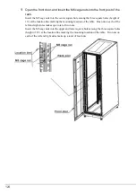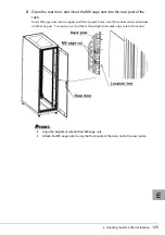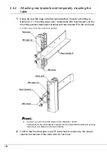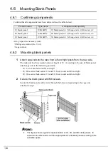
4 Handling the Rack after Installation
127
E
`
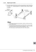
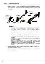
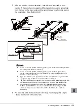
Front brackets L and R are part of the table.
3
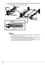
Insert the hooks at the front of the front brackets L and R into the square
holes right above the M6 cage nuts that were attached in step 2 according
to Section 4.4.1, "Inserting cage nuts."
Place the rear of the table on rear brackets L and R that were attached in step 1.
4
Confirm that the heights of the left and right square holes into which the
hooks were inserted are the same.
`
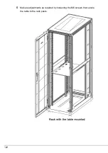
Since the table is only provisionally mounted, refrain from placing any loads on it.
Summary of Contents for 1740
Page 1: ...J E ...
Page 15: ...3 ラックの構成と設置 15 J 3 3 リヤドアの開き方 1 扉用キーを回し ラックハンドルを持ち上げ 手前に引きます ...
Page 28: ...28 1 マイナスドライバの先端をケージナットの爪とラック柱の間に挿入して ケージナットの爪に押し込みます 2 マイナスドライバを押し下げて取り外します ...
Page 36: ...36 8 富士通ロゴを取り付けます 富士通ロゴを扉の裏から M4 ネジで固定します 標準的な取り付け位置は 横方向寸法が 103 縦方向寸法が 122 です ࡀࠫ ን ㅢࡠࠧ ...
Page 54: ...54 5 必要に応じてラックの柱に固定している M6 ネジを緩め 再調整をしてく ださい ...
Page 63: ...4 ラック設置後の取り扱いについて 63 J 7 必要に応じてラックの柱に固定している M6 ネジを緩め 再調整をしてく ださい ...
Page 67: ...4 ラック設置後の取り扱いについて 67 J 図は 1U 2U 3U 用をまとめて表示していますが 実際の取り付けは空きスペー スに応じて 適切なサイズを選択し 取り付けてください ...
Page 68: ...68 ...

