


Rotational
speed
Run
command
DC link
bus voltage
Current
Time
ON
OFF
400ms
1500r/min
540V
20A
50V
Time
Rotational
speed
Current
2s
10A
600r/min
Holding torque generation
Variations according to load
Creep speed
Rotational
speed
Current
Time
Speed
Conveying distance
Load
torque
200ms
500r/min
200%
0
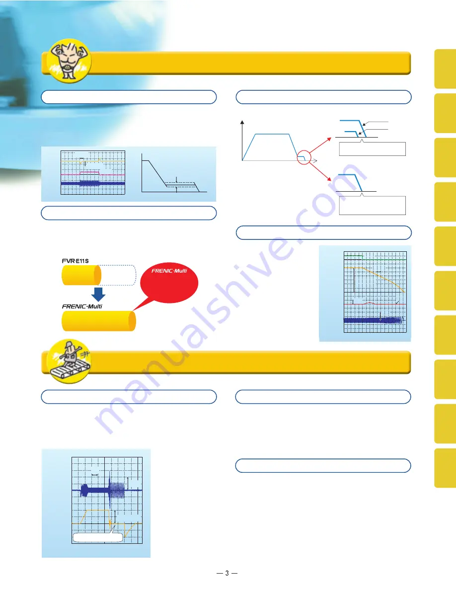
■
With speed feedback
Load: Small
Load: Large
The speed just before positioning
varies, so positioning accuracy drops.
The speed just before positioning is
stabilized, and so positioning accuracy
is improved.
Speed
Conveying distance
0
Through "slip compensation control" + "voltage tuning," speed
control accuracy at low speeds is improved. This minimizes
variations in speed control accuracy at times when the load
varies, and since the time at creep speeds is shortened,
single cycle tact times can be shortened.
The inverter controls the
energy level generated
and the deceleration time,
and so deceleration stop
can be accomplished
without tripping due to
overvoltage.
●
CPU speed comparison
The highest standards of control and performance in its class
The highest level CPU of any inverter is used. Computation
and processing capacity is doubled over the previous
inverter, improving speed control accuracy.
64
MHz
32
MHz
Equipped with the highest level CPU for its class!
Shortened setting time in slip compensation control
Compatible with PG feedback control
Tripless deceleration by automatic deceleration control
has
doubled
processing
capacity compared with
the previous model.
!
Optimum for the operations specific to vertical and horizontal conveyance
!
Impacts are detected mechanically and not only can the
inverter's operation pattern be set on coast-to-stop or
deceleration stop, but switching from torque limitation to
current limitation and generating a holding torque (hit-and-
stop control) can be selected, making it easy to adjust brake
application and
release timing.
Hit-and-stop control is realized more easily!
■
At brake release time
After the motor operates, torque generation is detected and
signals are output.
■
At brake application time
Brake application that matches the timing can be done,
and so mechanical brake wear is reduced.
Inclusion of a brake signal makes it even more convenient.
Inverters are equipped with two limit operations, "torque
limitation" and "current limitation," so either can be selected to
match the equipment you are using the inverter with.
■
Torque limitation
In order to protect mechanical systems, this function
accurately limits the torque generated by the motor.
(Instantaneous torque cannot be limited.)
■
Current limitation
This function limits the current flowing to the motor to
protect the motor thermally or to provide rough load
limitation. (Instantaneous current cannot be limited. Auto
tuning is not required.)
Limit operations can be selected to match your equipment!
■
Without speed feedback
<Example of conveyor operation pattern>
inverters can be used for multiple purposes
!
■
Improved speed control accuracy
improves conveyor positioning
accuracy.
■
Positioning time can be shortened.
■
Improves measuring accuracy on a
scale.
Specifications
Functions
Settings
Keypad
Operations
Basic
Wiring Diagram
Terminal
Functions
Protective
Functions
Options
Peripheral Equipment
Connection Diagrams
Warranty
External
Dimensions


