55
4-14. [F3] LCD Adjustment
<Step 1>
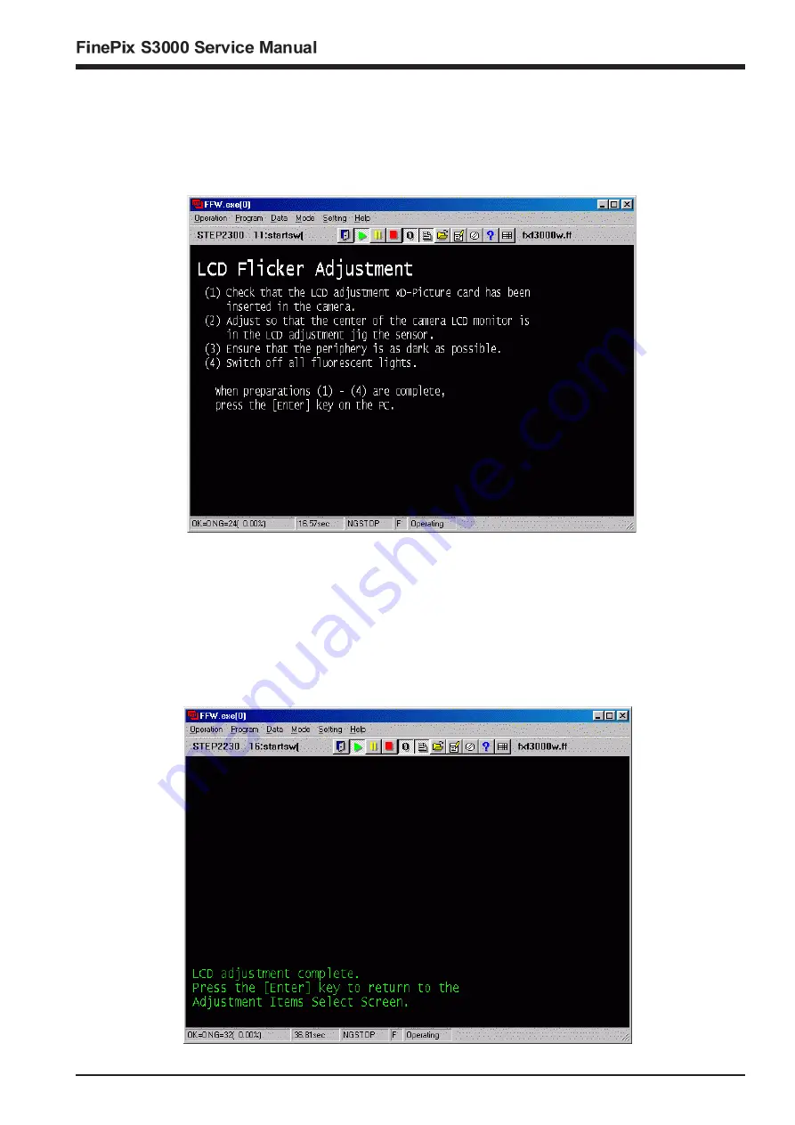
Select [F3] LCD Adjustment on the [Adjustment Items Select] screen (Fig.5).
—> The [LCD Adjustment Preparation] screen appears.
<Step 2>
Run the adjustment in accordance with the instructions on the screen.
<Note>
(1)
Refer to the Setup Manual supplied with the jig for details of setting up the LCD automatic adjustment jig with the PC.
(2)
If the LCD flicker image xD-Picture card has not been inserted in the camera, return to the [Jig Mode Setup] screen,
select the Jig mode again, and run LCD Adjustment.
—> LCD Adjustment is executed.
—> Write the adjustment data to the flash ROM when adjustment has been completed correctly.
—> The [LCD Adjustment Complete] screen appears.
<Fig. LCD1>
<Step 3>
<Fig. LCD2>
4.Adjustments
Summary of Contents for Finepix S3000
Page 7: ...7 1 3 Names of External Components ...
Page 19: ...19 3 Schematics 3 4 Block Diagram ...
Page 25: ...25 3 Schematics 3 7 Circuit Diagrams 3 7 1 DCDC Block Circuit ...
Page 26: ...26 FinePix S3000 Service Manual 3 Schematics 3 7 2 PROCESS Block Circuit ...
Page 27: ...27 3 Schematics 3 7 3 CAM Block Circuit ...
Page 28: ...28 FinePix S3000 Service Manual 3 Schematics 3 7 4 EVF Block Circuit ...
Page 29: ...29 3 Schematics 3 7 5 STROB Block Circuit ...
Page 30: ...30 FinePix S3000 Service Manual 3 Schematics 3 7 6 LCD Block Circuit ...
Page 31: ...31 3 Schematics 3 7 7 MOTOR Block Circuit ...
Page 32: ...32 FinePix S3000 Service Manual 3 Schematics 3 7 8 KEY IO Block Circuit ...
Page 33: ...33 3 Schematics 3 7 9 KEY IC Block Circuit ...
Page 35: ...35 3 Schematics 3 7 13 RSW Block Circuit 3 7 12 KSW Block Circuit 3 7 14 VCON Block Circuit ...
Page 54: ...54 FinePix S3000 Service Manual Step 6 Fig BATT5 4 Adjustments ...
Page 66: ...66 FinePix S3000 Service Manual MEMO ...
Page 82: ...26 30 Nishiazabu 2 chome Minato ku Tokyo 106 8620 Japan FUJI PHOTO FILM CO LTD ...


