background image

66

FinePix A310 Service Manual

6.Parts List

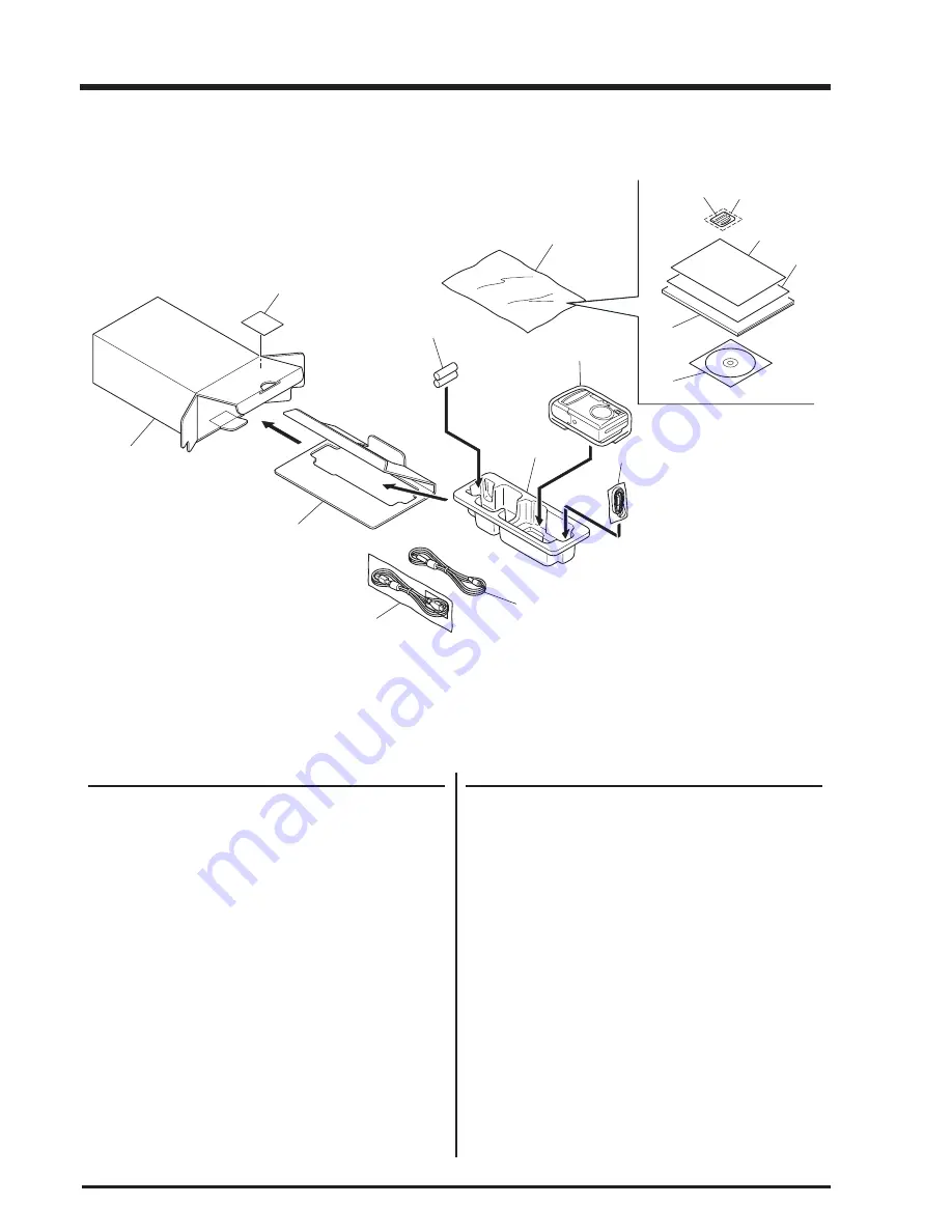
6-1-7.For CH model

Ref No.

Parts No.

Description

Comment

Ref No.

Parts No.

Description

Comment

A101 FZ05228-200

UNITARY U.BOX

A102 FZ05234-100

PARTITION PAD

A103 BB06392-100

3- LABEL BLANK

A104 FZ05229-100

SHEET MOLD

A105 BB07747-100

HDPE BAG 140*160

A106 FZ04792-100

ALKALINE BATTERY

A107 FZ04832-100

WIRE HARNESS(USB)

A108 FZ05262-100

WIRE HARNESS(VIDEO)

A109 BB04589-100

HAND STRAP

A110 AZF0000-101

LDPE BAG NO.10

A111 BL00298-100

INFORMATION SHEET

A112 BL00254-600

MANUAL (CHA)

A113 BF04146-100

XDCARD 16MB ASSY

A114 BL00209-100

CASE

A115 FZ05157-101

CD-ROM

A116 BL00313-200

INFORMATION SHEET2

A112

A105

A110

A106

A103

A113

A114

A116

A115

A101

A102

A107

A108

A109

A104

A111

Summary of Contents for FinePix A310 AS

Page 1: ...AS US CA GE CH JP Model THE COMPONENTS IDENTIFIED WITH THE MARK ON THE SCHEMATIC DIAGRAM AND IN THE PARTS LIST ARE CRITICAL FOR SAFETY PLEASE REPLACE ONLY WITH THE COMPONENTS SPECIFIED ON THE SCHEMAT...

Page 2: ...the original problem perform the following safety check before return the product to the costomer 1 Check the area of your repair for unsoldered or poorly sol dered connections Check the entire board...

Page 3: ...K Schematic Diagram 26 3 17 FLASH BLOCK Schematic Diagram 27 3 18 MAIN PWBASSY Component Locations 28 3 19 SUB PWBASSY Component Locations 28 4 Adjustments 29 4 1 Adjustment Procedure of Parts Replace...

Page 4: ...per second without sound Storage media xD Picture Card 16 32 64 128 256 MB File format Still image JPEG Exif ver 2 2 Design rule for Camera File System compliant DPOF compatible Movie AVI format Motio...

Page 5: ...ecial video cable 2 5 mm dia mini plug to pin plug Approx 1 5 m 1 Cradle adapter for FinePix A310 1 USB Interface Set 1 CD ROM Software for FinePix SX 1 Special USB cable with Noise Suppression core 1...

Page 6: ...ts movie files at 10 consecutive frames per second a rate that is expressed as 10 fps By comparison TV images are played at 30 fps JPEG Joint Photographics Experts Group A file format used for compres...

Page 7: ...od mount Viewfinder Battery cover Viewfinder lamp LCD monitor DISP button Macro button Mode dial Flash button Strap mount MENU OK button BACK button Power switch VIDEO OUT Video output socket Self tim...

Page 8: ...A310 Service Manual 2 Disassembly 8 2 Disassembly 2 1 Internal Components CABINET REAR ASSY MAIN PWB ASSY LENS UNIT CABINET FRONT ASSY BATTERY HOLDER BATTERY LID FLASH UNIT SUB PWB ASSY PSW PWB ASSY L...

Page 9: ...y cover 3 Raise the R PANEL ASSY in the direction of the arrow Assembly Set the mode dial to the camera position and assemble it Assemble in the reverse order to disassembly Note Always ensure that th...

Page 10: ...he direction of the arrow 3 Remove the connector 2 4 Removing the MAIN PWB ASSY Disassembly 1 Remove the FFC 2 Remove the NAIN PWB in the direction of the arrow taking care not caught of the shutter b...

Page 11: ...LDER in the direction of the arrow 3 Remove the BATTERY SHAFT Assembly Assemble in the reverse order to disassembly 2 6 Removing the Lens Unit Disassembly 1 Move the barrier stopper in the direction o...

Page 12: ...e order to disassembly 2 8 Removing the SW PWB Assy Disassembly 1 Remove the screw M1 7x3 5 2 Remove in the SW PWB Assy direction of the arrow Disassembly 1 Remove the two screws M1 7x3 5 2 Remove the...

Page 13: ...arrow 2 Remove the screw M1 7x3 5 3 Remove the LINK Assy in the direction of the arrow 1 1 2 3 Assembly Assemble in the reverse order to disassembly 2 10 Removing CCD PWB Assy Disassembly 1 Remove tw...

Page 14: ...acteristics of variable resistors and semi fixed resistors are not displayed 3 2 Basic Block Names and Functions Part name Block name Function LENS CONST CCD BLOCK CCD output MAIN PWB ASSY CAMERA BLOC...

Page 15: ...LSI Also the 10 bit image data input to this LSI is used for calculations by the auto calculation unit and sent to the ACS2 IC102 CCD processing IC of the CAMERA BLOCK so as to obtain a suitable AE AW...

Page 16: ...to LCD KEY_STB SI SO SCLK SIO SCLK KEY_SIO IC1 FFM MS3890 MotorDrv MITSUBISHI M50233HP IRIS_SPD FMPS ZMPS to MOTOR Drv XCS MEDIA LCD IBUF SEL USB CPU Core Memory Ctrl Local BUS Memory Ctrl Serial JPEG...

Page 17: ...M A DS5 11 11 DS5 FM B 5 5 FM B DCLK 12 12 DCLK FM_A 6 6 FM_A VSYNC 13 13 VSYNC FM_B 7 7 FM_B HSYNC 14 14 HSYNC ZPI_C 8 8 ZPI_C AVDD 15 15 AVDD LED_3 3V 9 9 LED_3 3V VLED 16 16 VLED ZPI_E 10 10 ZPI_E...

Page 18: ...0 Service Manual 3 Schematics GND CCD_OUT GND GND GND GND 16V 16V RS H1 H2 H3 H4 H5 H6 OFD 8V 8V V1A V1B V1C V1D V2 V3A V4 LM V3B V3C V3D CN1 NM 3 7 POWER SW BLOCK Schematic Diagram 3 6 CCD BLOCK Sche...

Page 19: ...19 FinePix A310 Service Manual 3 Schematics 3 8 CAMERA BLOCK Schematic Diagram...

Page 20: ...20 FinePix A310 Service Manual 3 Schematics 3 9 PROCESS BLOCK Schematic Diagram...

Page 21: ...21 FinePix A310 Service Manual 3 Schematics 3 10 POWER BLOCK Schematic Diagram...

Page 22: ...22 FinePix A310 Service Manual 3 Schematics 3 11 VIDEO BLOCK Schematic Diagram...

Page 23: ...23 FinePix A310 Service Manual 3 Schematics 3 12 KEY IC BLOCK Schematic Diagram...

Page 24: ...24 FinePix A310 Service Manual 3 Schematics 3 13 KEY SW BLOCK Schematic Diagram 3 14 R SW BLOCK Schematic Diagram...

Page 25: ...25 FinePix A310 Service Manual 3 Schematics 3 15 MOTOR BLOCK Schematic Diagram...

Page 26: ...26 FinePix A310 Service Manual 3 Schematics 3 16 LCD BLOCK Schematic Diagram...

Page 27: ...27 FinePix A310 Service Manual 3 Schematics 3 17 FLASH BLOCK Schematic Diagram...

Page 28: ...28 FinePix A310 Service Manual 3 Schematics 3 18 MAIN PWB ASSY Component Locations 3 19 SUB PWB ASSY Component Locations Side A Side B...

Page 29: ...adjustment common to FinePix 6800Z Conversion lens f 600mm ZJ00007 100 AF adjustment common to 8mm VTR FinePix 500 Lens holder ZJ00008 100 AF adjustment common to 8mm VTR FinePix 500 Stand ZJ00009 10...

Page 30: ...temperature measurement Filter LB140 and pattern box in direct contact Adjust color temperature of pattern box to 6100 50K with filter LB140 in contact with color thermometer 2 Luminance 160 5cd m2 wi...

Page 31: ...uses a USB interface for communica tions with the PC the USB Jig Driver must first be installed on the PC before the PC adjustment software can be run As the USB Jig Driver is the same for all models...

Page 32: ...tware will not run if the user program is overwritten Fig E Fig F Step 1 Double click on the FFW exe file Fig E in the adjustment software folder to display the FFW Start up Screen Fig F Step 1 Insert...

Page 33: ...change Do t check Use Japanese font Do t check Don t show OK NG Check or Don t check Note If Disable OKNG display on the PC screen Fig H is set to OFF the PC screen displays OK if adjustment is OK and...

Page 34: ...User program help FOCAS Do not use with adjustment software Version Basic software version information Cautions for Adjustment Caution 1 Running End setting returns the camera to the Product mode from...

Page 35: ...to display the adjustment software start up screen Fig 1 Run the adjustment in accordance with the instructions on the screen Fig 2 The FFW exe Start up Screen Fig 1 window appears Step 2 Press the En...

Page 36: ...e Jig Mode Setup Procedure Screen Fig 3 appears Step 4 Set the camera in the Jig mode and press the Enter key The Firmware Display Screen Fig 4 appears Firmware Confirmation Screen Step 5 Press the En...

Page 37: ...on CCD data input Press the F 4 key Camera adjustment Press the F 5 key AF adjustment Press the F 6 key Flash adjustment Press the F 7 key VIDEO adjustment Press the F11 key Battery voltage adjustment...

Page 38: ...first line are discarded and 2 to5 digits are used The four digits from the top in the second line are then appended to form the CCD data file name Record this file name Cautions 1 The CCD damage dat...

Page 39: ...ntered 3 Insert the CCD data floppy disk in the floppy disk drive A drive When preparations are complete press the Enter key Click on the OK button CCD Data input begins When adjustment is completed s...

Page 40: ...level adjustment Step 1 Select F5 from the Adjustment Items Select Screen Fig 5 press F5 on the PC keyboard The Shutter Adjustment Preparation Screen Fig 9 appears Caution When adjusting the camera me...

Page 41: ...on the screen Fig 11 When preparations are complete press the Enter key Camera adjustment moves to the next stage Step 4 Remove the LB140 filter in accordance with the instructions on the screen Fig 1...

Page 42: ...Manual 4 Adjustments Step 5 The screen in Fig 13 appears when adjustment is completed satisfactorily Press the Enter key The system returns to the Adjustment Items Select Screen Fig 5 Camera adjustme...

Page 43: ...fter replacing the LENS CONST or MAIN PWB ASSY always run AF adjustment after camera adjustment 3 Do not conect VIDEO cable while adjusting AF Step 1 Select F6 from the Adjustment Items Select Screen...

Page 44: ...tions are complete press the Enter key Adjustment proceeds to backlash adjustment zoom reset adjustment and AF adjustment and the AF Ad justment Complete Screen Fig 16 appears Step 4 Press the Enter k...

Page 45: ...influence 2 When adjusting the flash measure distance from the front of the camera body 3 Always run flash adjustment after completing CAMERA adjustment Step 1 Select F7 from the Adjustment Items Sel...

Page 46: ...ment start Screen Fig 18 appears Step 3 When preparations are complete press the Enter key The Flash Adjustment Complete Screen Fig 19 appears Step 4 Press the Enter key The system returns to the Adju...

Page 47: ...as shown in the connection diagram Select F11 VIDEO Adjustment on the Adjustment Items Select screen Fig 5 The VIDEO Adjustment Preparation screen Fig 21 appears Step 2 When preparations are complete...

Page 48: ...A310 Service Manual 4 Adjustments The LCD Adjustment Complete screen Fig 22 appears Step 3 Press the Enter key The system returns to the Adjustment Items Select Screen Fig 5 LCD adjustment is complet...

Page 49: ...between the adjustment software and the camera and the adjustment software may produce an error Restart the adjustment software in this case Step 1 1 Connect as shown in the connection diagram Run th...

Page 50: ...age Setting Screen 2 15V Fig 24 appears Step 3 Set input voltage battery preend voltage adjustment and press the Enter key The Battery Voltage Setting Screen 2 05V Fig 25 appears Step 4 Set input volt...

Page 51: ...creen 3 00V Fig 26 appears Step 5 Set input voltage at 3 00V and press the Enter key Fig 26 The Battery Voltage Setting Complete Screen Fig 27 appears Step 6 Press the Enter key The system returns to...

Page 52: ...mode and checking on the displayed Firmware Version Check Screen Fig 4 Step 1 Select F8 from the Adjustment Items Select Screen Fig 5 press the F8 key on the keyboard The Download start Screen Fig 28...

Page 53: ...e new firmware when power is switched OFF ON Step 4 The Jig Mode Setup Screen Fig 2 set the camera in the jig mode and press the Enter key twice The Firmware Version Check Screen Fig 4 appears this sc...

Page 54: ...e PC the PC will be unable to identify each USB device thus preventing operation Step 1 Select F12 from Adjustment item Select Screen Fig 5 ie press the F12 key on the computer The End Setting Start S...

Page 55: ...third character from left side of the serial number shows the destination Select it according to the destination Press the B key to select US CA model Press the Enter key This example uses Destination...

Page 56: ...nual 4 Adjustments Fig 34 Step 4 Follow instruction on the Repair site Select Screen Fig 34 and press the H key This example uses USA site Fig 35 The USB ID USA site selected Screen Fig 35 is appears...

Page 57: ...t Mode Setting Screen Fig 36 When the settings are completed normally they are saved to the flash ROM and the FinePix A310 Adjustment finished Screen Fig 37 is appears Step 8 1 Remove jig and all cabl...

Page 58: ...a 1 Place battery in camera 2 Insert card and close card cover 3 Set mode dial to still photography mode 4 Turn power ON 5 If the date set message appears press Cancel 1 Apply an appropriate shock to...

Page 59: ...eep LOW Language Engrish Pixels 1M normal Photography mode A mode Date Not set 3 Inspection battery inspection xD Picture card not inserted in camera 4 Battery cover closed 5 LCD surface free of conta...

Page 60: ...100 WIRE HARNESS VIDEO A109 BB04589 100 HAND STRAP A110 FZ05264 100 CRADLE ADAPTER SU440 A111A BB16335 300 DEST LBL EG J FG A111B BB16335 C00 DEST LBL EG C FG A112 AZF0000 101 LDPE BAG NO 10 A113 BL00...

Page 61: ...00 CRADLE ADAPTER A310 A111A BB16335 200 DEST LBL EU J FG A111B BB16335 B00 DEST LBL EU C FG A112 AZF0000 101 LDPE BAG NO 10 A113 BL00298 100 INFORMATION SHEET A114 BL00254 200 MANUAL ENG A115 BL00254...

Page 62: ...5229 100 SHEET MOLD A105 BB07747 100 HDPE BAG 140 160 A106 FZ04792 100 ALKALINE BATTERYLR6GA 2STH A107 FZ05282 100 WIRE HARNESS USB A108 FZ05262 100 WIRE HARNESS VIDEO A109 BB04589 100 HAND STRAP A110...

Page 63: ...D STRAP A110 FZ05264 100 CRADLE ADAPTER A310 A111A BB16335 100 DEST LBL US J FG A111B BB16335 A00 DEST LBL US C FG A112 AZF0000 101 LDPE BAG NO 10 A113 BL00298 100 INFORMATION SHEET A114 BL00254 200 M...

Page 64: ...62 100 WIRE HARNESS VIDEO A109 BB04589 100 HAND STRAP A110 FZ05264 100 CRADLE ADAPTER A310 A111A BB16335 400 DEST LBL CA J FG A111B BB16335 D00 DEST LBL CA C FG A112 AZF0000 101 LDPE BAG NO 10 A113 BL...

Page 65: ...4 FZ05229 100 SHEET MOLD A105 BB07747 100 HDPE BAG 140 160 A106 FZ04792 100 ALKALINE BATTERY A107 FZ05282 100 WIRE HARNESS USB A108 FZ05262 100 WIRE HARNESS VIDEO A109 BB04589 100 HAND STRAP A110 FZ05...

Page 66: ...A105 BB07747 100 HDPE BAG 140 160 A106 FZ04792 100 ALKALINE BATTERY A107 FZ04832 100 WIRE HARNESS USB A108 FZ05262 100 WIRE HARNESS VIDEO A109 BB04589 100 HAND STRAP A110 AZF0000 101 LDPE BAG NO 10 A1...

Page 67: ...BATTERY A107 FZ04832 100 WIRE HARNESS USB A108 FZ05262 100 WIRE HARNESS VIDEO A109 BB04589 100 HAND STRAP A110 FZ05264 100 CRADLE ADAPTER SU440 A111 AZF0000 101 LDPE BAG NO 10 A112 BL00254 100 MANUAL...

Page 68: ...SSY M219 FZ05226 101 WIRE HARNESS M220 BB15972 100 BATTERY HOLDER M221 BB15973 100 BATTERY SW PLATE M222 BB15974 100 BATTERY LID M223 BB14550 100 TERMINAL PLATE M224 BB14551 100 TERMINAL PSP M225 BB15...

Page 69: ...9 100 BUSTERAID R4N 01 56 2X16 5T08AS M306 BB15553 100 CONDENSER SHEET M307 BB16600 101 AL SHEET M308 FZ05372 100 BUSTERAID R4N 01 30X25T08AS M309 BB13209 100 INSULATING TUBE M310 BF04420 100 LCD CONS...

Page 70: ...7 BB15965 100 OPERATIONBUTTON M408 BB15966 100 LEDGUIDE M409 ATG1723 5ND SCREW M410A BB15980 100 PRODUCTLBL M410B BB15980 200 PRODUCTLBL M411 BB15982 100 3ULR BT2P 1 7 5 0GN M412 BB17212 100 SEET R CA...

Page 71: ...962 100 MODEDIAL M404 BB15963 100 MODE LABEL M405 BB15964 100 MODEPSP M406 BB14572 100 ZOOMBUTTON M407 BB15965 100 OPERATIONBUTTON M408 BB15966 100 LEDGUIDE M409 ATG1723 5ND SCREW M410 BB15980 100 PRO...

Page 72: ...T SWITCH 1Circuit 1P SW504 FZ02084 100 TACT SWITCH 1Circuit 1P SW505 FZ02084 100 TACT SWITCH 1Circuit 1P SW506 FZ02084 100 TACT SWITCH 1Circuit 1P SW507 FZ02084 100 TACT SWITCH 1Circuit 1P SW508 FZ047...

Page 73: ...dix 7 Appendix 7 1 List of Related Technical Updates Issued To ensure that after sales srevice is performed accuratety keep a record here of the technical updates issued that cover this device Technic...

Page 74: ...26 30 Nishiazabu 2 chome Minato ku Tokyo 106 8620 Japan FUJI PHOTO FILM CO LTD...

Reviews: