background image

11 


M2


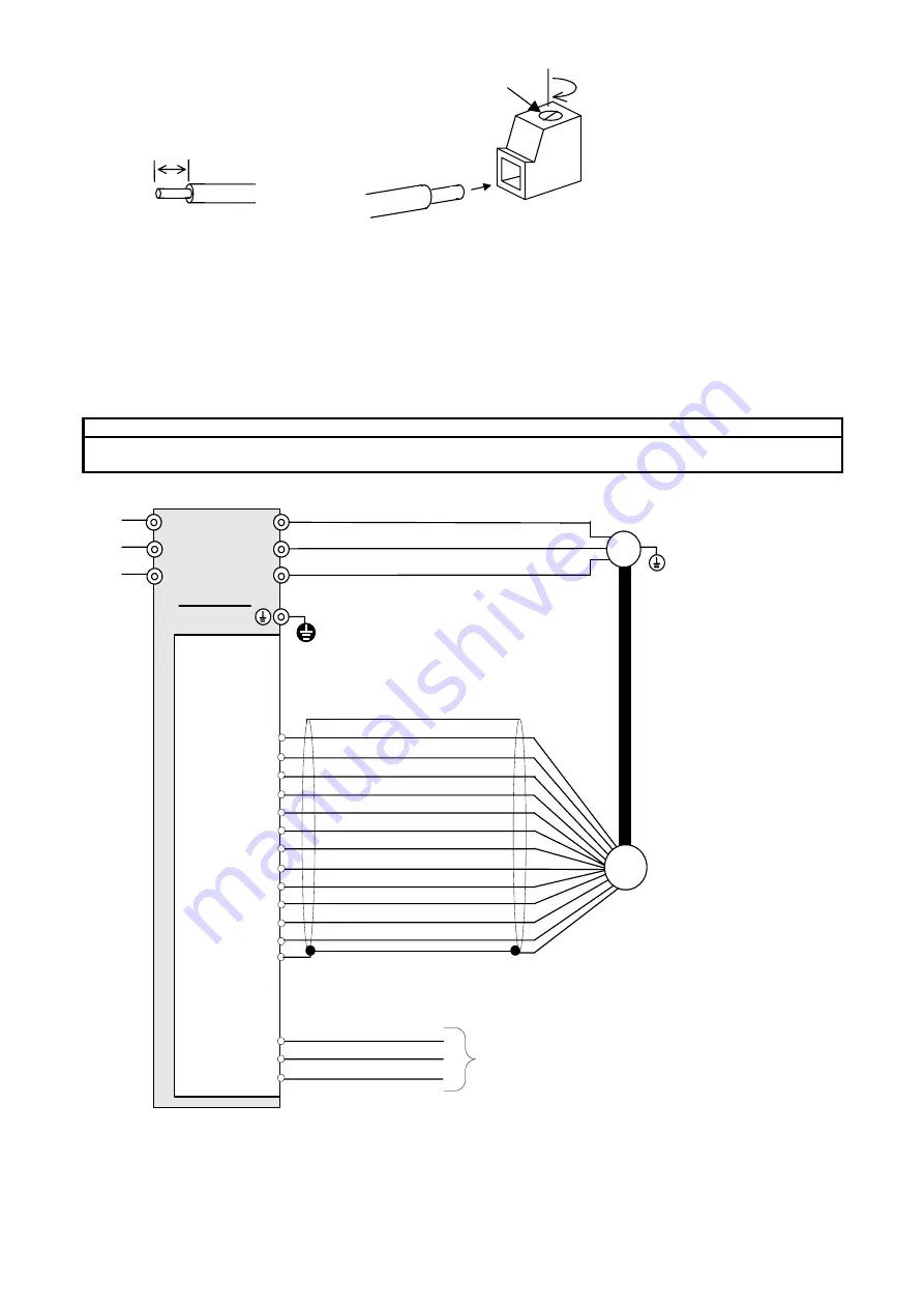
4.3  Basic Wiring Diagram 


CAUTION


  Keep the power supply voltage of encoder in the specification voltage of encoder. 

There is a risk of failure.


L1/R

L2/S

L3/T

U

V

W

M

CK-
DT+
DT-

FRN-LM1S

G

OPC-LM1-PS1

PA-
PB+
PB-

CK+

PO

PA+

PO

CM
CM

Encoder

FPA
FPB

CM

CM


User

Controller


Figure 4.1    Basic Wiring Diagram 

7(mm) 

Connection of Wiring on Option 

Terminal Side. 

Summary of Contents for OPC-LM1-PS1

Page 1: ...lly operate the equipment Read this instruction manual and understand the description before installing connecting wiring operating or performing maintenance and inspection of the option Keep this ins...

Page 2: ...card with wet hands otherwise accident or electric shock may occur No foreign matter such as screws metal patches lint chips and dust in the option card There is risk of fire or accident Do not damag...

Page 3: ...Terminal Function and Specifications 8 2 5 Control Specifications 8 3 Applicable Encoder 9 3 1 Specifications of Applicable Encoder 9 3 2 Encoder Installation and Signal 9 4 Wiring 10 4 1 Wiring Leng...

Page 4: ...etails refer to the Multi function Keypad Instruction Manual INR SI47 1092 E Use the FRENIC Loader option for the FRENIC Lift and click the System monitor tab on the Operation Status Monitor window Fo...

Page 5: ...G Turn off the power and wait for at least five minutes before starting installation Further check that the LED monitor is unlit and check that the DC link bus voltage between the P and N terminals is...

Page 6: ...the four spacers and CN1 on the back of the OPC LM1 PS1 into the spacer holes and connector CN1 on the control circuit board in the inverter Visually check that the spacers and CN1 are firmly inserted...

Page 7: ...m2 or less per year 86 to 106 kPa in storage Atmospheric pressure 70 to 106 kPa during transportation 1 Assuming a comparatively short storage period e g during transportation or the like 2 Even if th...

Page 8: ...he inverter must not be subjected to sudden changes in temperature that will cause condensation to form Altitude 1 000 m max Note Vibration 3 mm Max amplitude 2 to 9 Hz 9 8 m s2 9 to 20 Hz 2 m s 2 20...

Page 9: ...put frequency Max 50 kHz Differential input signal PA PA PB PB 0 6V to 1 2V CK Communication clock non inverting CK Communication clock inverting Clock transmission DT Communication data non inverting...

Page 10: ...oder Encoder power supply Encoder model HEIDENHAIN ECN1313 or its equivalent 3 2 Encoder Installation and Signal The encoder shall rotate in the direction shown in Figure 3 1 when terminal FWD is ON E...

Page 11: ...is 10 m or more PA green black A PA yellow black A PB blue black B PB red black B CK purple CLOCK CK yellow CLOCK DT gray DATA DT pink DATA Wiring of the option card and the encoder The wiring of the...

Page 12: ...coder in the specification voltage of encoder There is a risk of failure L1 R L2 S L3 T U V W M CK DT DT FRN LM1S G OPC LM1 PS1 PA PB PB CK PO PA PO CM CM Encoder FPA FPB CM CM User Controller Figure...

Page 13: ...oder L36 ASR P Constant at high speed 2 0 It is necessary to adjust L38 ASR P Constant at low speed 2 0 It is necessary to adjust 5 2 Procedure of Magnetic Pole Position Offset Tuning You have to exec...

Page 14: ...the FWD key starts tuning The EXECUTING is displayed on the monitor of the MFKP during the tuning The EXECUTING disappears indicating that it is the end of tuning The L03 data automatically returns to...

Page 15: ...3 2 Adjust the following parameters to eliminate vibration and the rollback becomes small The following table shows the tendency to the phenomenon by setting of the parameter Function Code Code Settin...

Page 16: ...ed inverter unbalanced load compensation works correctly Using analog speed command Time 0 ON FWD Release Brake Reference speed pre ramp Lift controller output F24 F23 Time 0 Reference speed final Act...

Reviews: