35
5.6.3 Run/Idle
Flag Behavior
EtherNet/IP clients (such as PLCs) have
the option of adding a 32-bit “run/idle”
header to all class 1 (I/O) data packets
sent to devices. Bit 0 of this header is
called the “run/idle flag” by the EtherNet/IP
specification, and is intended to signify
when the client is in a “running” state or an
“idle” state. A running state (run/idle flag = Run) is indicated whenever the client is performing its normal
processing (e.g. scanning its ladder logic). An idle state (run/idle flag = Idle) is indicated otherwise. For
example, Allen Bradley ControlLogix PLCs will set their run/idle flag to Idle whenever their processor
keyswitch is placed in the “PROG” position, presumably in preparation to receive a new application
program from RSLogix.
The behavior of EtherNet/IP devices when they receive I/O data from a controller with the run/idle flag
set to Idle is not specified in the EtherNet/IP specification. The interface card allows the option of two
different behavioral responses when a run/idle flag = Idle condition is received, depending on the state of
the checkbox indicated in Figure 42.
•
If the checkbox is cleared (default setting), then the interface card will maintain the last I/O data
values received from the client. For example, if the inverter was being commanded to run prior to
the run/idle flag being set to Idle, then it will continue to run.
•
If the checkbox is checked, then the interface card will invoke its user-configured timeout
processing (refer to section 5.5.3).
5.6.4 Class 1 (I/O) Data Configuration Arrays
The interface card supports two different types of EtherNet/IP class 1 (I/O) data transfer. One type is
included with the implementation of the AC/DC drive profile, and requires no user configuration. The
other type, however, is entirely user-configurable, and is utilized when the client opens a connection to
the interface using assembly instances 100 and 150.
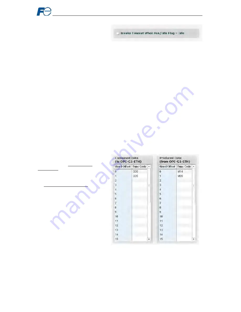
The user-configurable data arrays
consist of two separate elements (refer
to Figure 43.) The consumed data
configuration defines the structure of the
command data sent from the EtherNet/IP
controller (for example, a ControlLogix
PLC) to the inverter (O->T direction), and
the produced data configuration defines
the structure of the status data sent from
the inverter back to the controller (T->O
direction). These arrays allow the
creation of custom-built I/O data. Up to
32 command function codes can be sent
to the inverter, and up to 32 status
function codes can be sent back to the
controller. Each box in the “function
code” column is capable of containing an
inverter function code. Because all
inverter function codes are 16-bit data
elements, each box therefore represents
two bytes of consumed or produced
data.
Each of the function code array locations
are numbered 0-31 in the “word offset”
column. Clicking on a box in an array allows the user to enter a function code that will be referenced at
that location when data is either consumed from the controller or produced to the network. If an attempt
is made to enter an invalid function code, an error dialog box will appear. A blank value indicates that no
function code is referenced at that location, which will cause the corresponding consumed data to be
ignored and produced data to be a default value of 0.
As an example, looking at the default configuration shown in Figure 43, we can see that each array
contains two defined function codes. Therefore, up to 4 “meaningful” bytes of data can be both received
and sent (the qualifier “meaningful” is used here because the connection sizes configured in the
Figure 42: Run/Idle Flag Behavior Selection
Figure 43: EtherNet/IP Class 1 (I/O) Data Configuration
CTi Automation - Phone: 800.894.0412 - Fax: 208.368.0415 - Web: www.ctiautomation.net - Email: [email protected]


