


Page
29
of
42
Fuji Electric Europe GmbH
11. Settings
11.5 Additional settings for induction motor in open loop
- No-load current (function P06).
The no-load current (function P06) defines the value of the current of the motor when no load is applied to the motor
(exciting current).
Typical values of the no-load current range from 30 % of P03 up to 70 % of P03. In the majority of the cases the
value calculated by the auto-tuning procedure will be correct (when P04=3). In some cases the auto-tuning procedure
cannot be finished correctly (due to special behaviour of the motor). In this later case the value of P03 must be set
manually. For calculate no-load current you can use the formula
2
2
F05
*
1.47
1000
*
P02
P03
P06
Too low values in P03 will make that the motor does not have enough torque. Too high values will make that the
motor oscillates (this oscillation will cause a vibration in the motor that is transmitted to the cabin).
- Slip frequency (function P12).
The slip frequency function defines the value of the slip frequency of the motor. Is the key function for a good slip
compensation by the inverter; this means that this function is very important in open loop control of induction motors
for a good landing accuracy because it will ensure that the rotating frequency of the motor is the same regardless of
the load condition of the motor.
In the majority of the cases the value measured by the auto-tuning procedure will be correct. In some cases the auto-
tuning procedure cannot be finished correctly (due to special behaviour of the motor). In this later case the value of
P12 must be set manually.
To set function P12 manually we can calculate it from the following formula:
120
_
))
(
_
)
(
_
(
12
Poles
No
rpm
speed
Rated
rpm
speed
s
Synchronou
P
- Slip compensation gains (functions P09 for driving mode and P10 for braking mode)
The slip frequency can be also compensated in both driving and braking mode. The experimental method for adjust
these values is following. You need to test one floor level with cabin empty going up and down:
-
If the cabin speed going up is smaller than the desired speed (the cabin don’t reach floor level)
decrease 10% the value of P10 (braking mode).
-
If the cabin speed going down is higher than the desired speed (the cabin pass floor level) decrease
10% the value of P09 (driving mode).
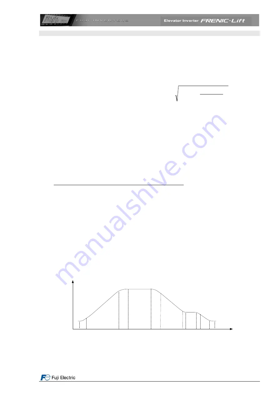
11.6 Setting the speed profile
The setting of the speed profile includes:
Travelling speed
Acceleration and deceleration times
S curves
For the rated speed, each intermediate speed and creep speed the acceleration, deceleration times and S curves can
be set independently. The setting of the S curve means the speed change in terms of percentage of the maximum
speed (F03) used for the acceleration change.
1
2
3
4
5
6
7
8
9
10
11
speed
Speed profile sections 1 to 11
time
Figure 27: Speed profile using creep speed.


