


Page
18
of
42
Fuji Electric Europe GmbH
(A,A,B,B)
7. Encoder
7.2 Option card OPC-LM1-IL for induction motors (with or without gear)
Application:
For induction motors with or without gear
The feedback encoder of the motor is line driver TTL (differential 5 VDC)
When the encoder signals are also connected (used by) the lift controller
Encoder technical data:
Supply voltage: +5 VDC ±5%
2 signals with 90° phase shift
Maximum input frequency: 100 kHz
Recommended pulse count: 1024 or 2048 pulses/rev (with high efficiency gearboxes
it is highly recommended to use encoders with 2048 pulses/rev)
Other characteristics and application requirements:
Maximum cable length: 20 m
Use only shielded cables
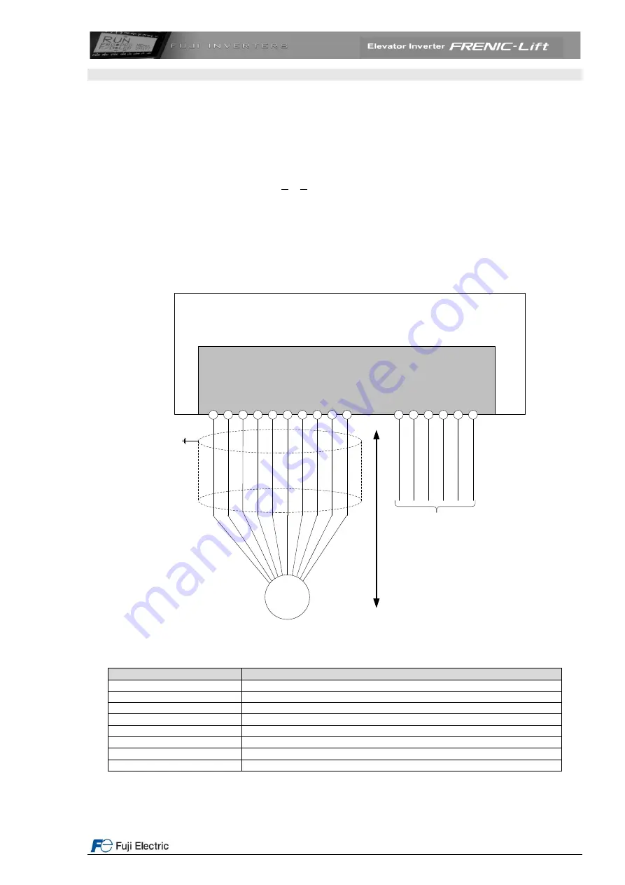
Figure 12: Option board connection
Table 14: OPC-LM1-IL connection terminals meaning
Terminal/signal names
Description
P0
Encoder voltage supply 5 VDC (maximum current 300 mA)
CM
Common 0 V
PA+
Phase A (square pulse)
PA-
Phase A inverted (square pulse)
PB+
Phase B (square pulse)
PB-
Phase B inverted (square pulse)
PZ+
Phase Z (square pulse)
PZ-
Phase Z inverted (square pulse)
The signal names may be different depending on the encoder manufacturer.
FRENIC-Lift
OPC-LM1-IL
M
a
x
im
u
m
c
a
b
le
le
n
g
th
2
0
m
PZ-
PZ+
PB-
PB+
PA-
PA+
CM
CM
PO
PO
Incremental
encoder
PZ-
PZ+
PB-
PB+
PA-
PA+
Encoder output signal
Line Driver signal
5 VDC to be connected
to the Lift controller
(Shaft copy)


