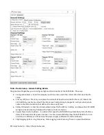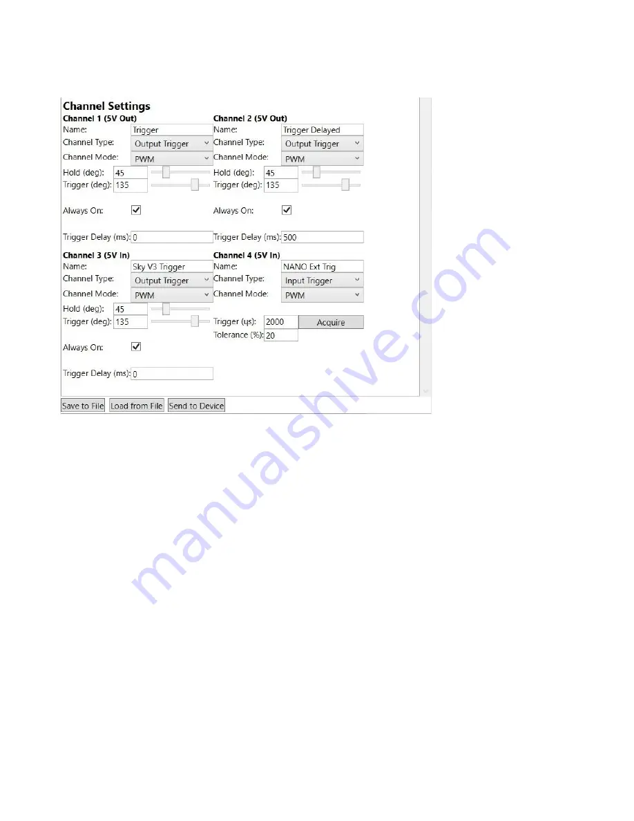
Channel Configuration for Default Configuration
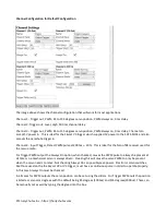
The image above shows the channel configuration that will work for most applications.
Channel 1 - Trigger out, PWM, 45 to 135 degrees servo position, PWM always on, 0 ms delay
Channel 2- Trigger out, Level, High, 500 ms channel delay
Channel 3 - Trigger out, PWM, 45 to 135 degrees servo position, PWM always on, 0 ms delay, Channel can
accept 5V power in. This is ideal for the Skycat V3 trigger which supplied 5V power to the SATS-MINI. and also
accepts the parachute trigger in.
Channel 4 - Input Trigger, Detect PWM pulse at - 20%. This is ideal for the Nano TBS receiver used for
the rescue radio.
For Trigger PWM output the Always On option, when checked, causes the PWM pulse to always be present at
all times so a mechanical servo is always driven. Clearing this will cause the servo PWM to only be present
when the servo needs to move. Not checking Always On can possibly save power. Electronic servo switches,
like those used on the the Skycat V2 or V3 trigger, must have a continuous pulse in order to operate properly.
In this case Always On must be checked.
In all cases for PWM outputs the servo position can be set using the sliders. For Trigger PWM outs the position
is listed as servo arm degrees with the default being 45 degrees (1000us) and 135 degrees(2000us). These can
be manually set as well by typing the degrees into the box.
© Fruity Chutes Inc - https://fruitychutes.com


