background image

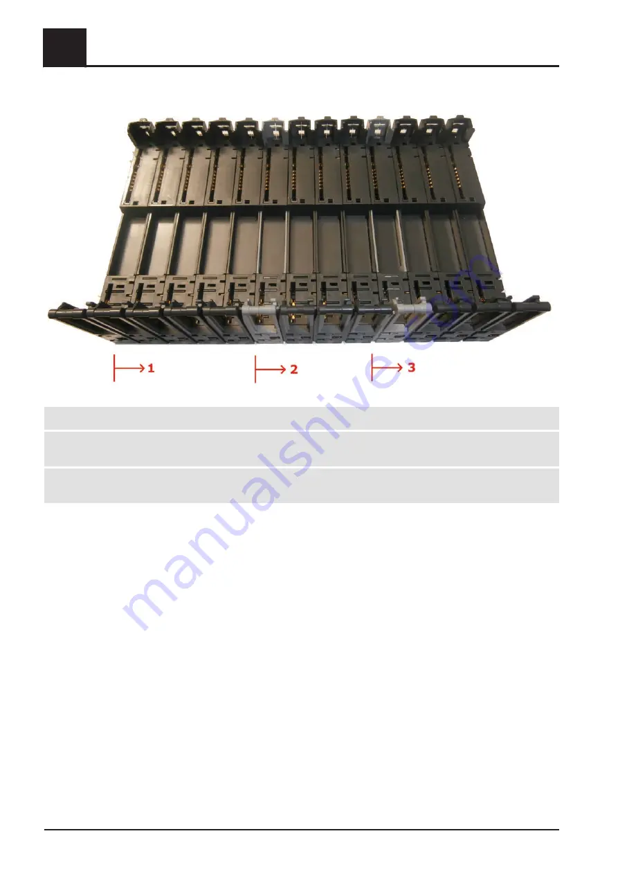
The image below shows one possible setup:

1

Start of the rack with the BR9300 module. The inputs/outputs are supplied up to point 2.

2

A PS2100 module needs to be inserted here to supply the subsequent inputs/outputs with 24V up to point 3. This

setup could, for example, be a locking unit.

3

A PS2100 module is inserted again here to supply the remaining inputs/outputs with 24V. This setup could, for

example, be another locking unit.


7

Electric components and wiring

PLC

100

Fröling GesmbH | A-4710 Grieskirchen, Industriestraße 12 | www.froeling.com

Summary of Contents for SPS 4000

Page 1: ...German operating instructions for technicians and operators Read and follow the instructions and safety information Technical changes typographical errors and omissions reserved B0960622_en Edition 17 10 2022 Fröling GesmbH A 4710 Grieskirchen Industriestraße 12 www froeling com ...

Page 2: ... tank distributor 1 4 29 Network circuit 1 2 30 Heating circuit 1 10 30 DHW tank 1 5 30 5 1 2 Settings for direct heat distribution 31 5 1 3 Storage tank 31 5 1 4 Network circuit 1 2 32 5 1 5 Heating circuit 1 10 34 5 1 6 DHW tank 1 5 35 5 2 System connection 36 5 2 1 Cascade 36 5 2 2 Boiler 1 5 36 5 3 Boiler 37 5 3 1 Modes 37 Boiler mode 37 External boiler controller 37 Chimney sweep 38 Extra hea...

Page 3: ...r discharge system 80 Discharge configurations 81 5 8 6 Ash removal 84 5 8 7 Flue gas treatment 85 5 8 8 Inputs outputs 86 5 8 9 Operation hours 88 5 8 10 Backup restore 88 6 Troubleshooting 89 6 1 Procedure in case of malfunctions 89 7 Electric components and wiring 90 7 1 PLC 90 7 1 1 Touchscreen 90 Connections 91 7 1 2 X20 module layout 92 7 1 3 X20 module types 95 BR9300 95 PS2100 98 BT9100 10...

Page 4: ...opment of our products means that there may be minor differences from the pictures and content If you discover any errors please let us know doku froeling com Subject to technical change About these instructions The range of functions of the SPS 4000 depends on the user level currently set These instructions show all the parameters that are available with full functionality in the Service user lev...

Page 5: ...re possible on hot surfaces and the flue gas pipe When work is carried out on the boiler Shut down the boiler according to procedure Boiler off operating status and allow it to cool down Protective gloves must usually be worn for work on the boiler and it should only be operated using the handles provided Insulate the flue gas pipes and do not touch them during operation The information on safety ...

Page 6: ...m status 2 Navigation area for quick switching between the start page and the individual menus 3 Display area for the selected menu 4 Area for status displays Ethernet USB etc 5 Quick selection area 6 Display of time and date 2 Overview of the basic functions Touch display 6 Fröling GesmbH A 4710 Grieskirchen Industriestraße 12 www froeling com ...

Page 7: ... If a parameter has the pen symbol beside it it means that the parameter can be adjusted If you open the parameter either the numeric keypad or a list box for changing the value of the parameter will appear Cancel icon Discards any values entered without saving and closes messages Accept icon To accept values entered without closing the change dialogue Confirm icon Confirms any values entered and ...

Page 8: ...ition The electric ignition is still active but no further material is inserted The boiler waits to see if fire is detected Heating The boiler is heating Slumber The boiler is shutting down Fuel is inserted periodically to maintain residual embers and to make it easier to reignite Shutdown Empty stoker The boiler is shutting down Combustion is continued in a controlled manner until the fuel in the...

Page 9: ...the combustion chamber can be heated by manually inserting fuel e g logs static state These states last until they are changed by interactions or other external influences All of the other states are only temporary and have a maximum duration Overview of the basic functions 2 Operating statuses Service manual SPS 4000 B0960622_en 9 ...

Page 10: ... shuts down the boiler in a controlled way After the shut down procedure the boiler switches to the OFF status switched off off The SPS controls the connected heating system All parts of the boiler are deactivated The chamber discharge system remains active 3 Operation Switching the boiler on off 10 Fröling GesmbH A 4710 Grieskirchen Industriestraße 12 www froeling com ...

Page 11: ...s is displayed here 3 List of the assigned current values with name and current status 4 Colour of the trend line assigned to the current value 5 For quick switching of line visibility Defines whether the trend line associated with the current value is displayed 6 Start stop automatic scrolling of the trend display left arrow right arrow to move the trend display along the time axis 7 Scaling of t...

Page 12: ...pdown field to select the current value 4 Specifies whether the current value is to be displayed as a trend line Visibility can be changed during the recording by tapping the eye icon 5 Defines whether the value axis is displayed in the trend 6 Defines the colour of the trend line 3 Operation Trend display 12 Fröling GesmbH A 4710 Grieskirchen Industriestraße 12 www froeling com ...

Page 13: ...nent is being controlled in manual mode The manual operation function is terminated by tapping on the green Automatic icon 3 4 System menu The system menu shows the menu items available depending on the user level and the system configuration The view is arranged in two columns and always shows two menu levels By tapping on a menu item in the left column the respective submenu is displayed in the ...

Page 14: ...ently set value Parameter is reset to this value if you cancel the entry 2 Displays the changed value 3 Setting range of the parameter The values can also be selected directly 4 Confirm icon to save and exit the dialogue Cancel icon to exit the dialogue without saving the entries Changing the parameter value There are different ways of entering values depending on the type of parameter increase re...

Page 15: ...The parameter value is saved and the setting dialogue closes Entering a value If a numeric keypad icon appears beside the parameter value in the display field you can enter the value directly Tap the numeric keypad icon or value field The Enter values window for parameters will appear Type in the relevant value on the numeric keypad Confirm your entry by tapping the confirm icon Operation 3 System...

Page 16: ... warning symbol or in the empty area next to the display field 3 6 Quick info Quick info is used to display the current operating values of the system and can be displayed at any time Tap the info symbol in the quick selection area The quick info is displayed and shows the last page displayed Select the desired system area by tapping on the tabs in the lower part of the menu Use arrow down and arr...

Page 17: ...k If an invalid code is entered e g 0 The display is locked for editing it is only possible to switch off the system and to switch the user level Operator Static code 1 Standard user level with all of the regularly required functions and parameters Expert Static code Additional parameters and manual operation are available Advanced diagnostic options are available The code for this user level is p...

Page 18: ...USB stick A USB stick with a licence file is required to switch to the Service user level The required file is available in the Fröling partner area for authorised users If the SPS 4000 detects a valid licence file on the connected USB stick it automatically switches to the Service user level Tapping the service icon displays the licence file data 3 Operation Switching user level 18 Fröling GesmbH...

Page 19: ...stomer services technician will use the PIN to generate a five digit one off password Enter the one off password and confirm Service user level is active until the user logs out or a set time has expired 3 9 Setting the date and time Tap the date and time area on the start screen The menu for setting the date and time will appear Tap the desired display value to change it Numeric keypad for changi...

Page 20: ... PLC Date Time Open Time settings parameter Set parameter value to NTP time server and save the setting Set the IP address of the desired time server and the respective time zone at the installation site Date Time By tapping on the date or time on the start screen the status of the synchronization is now displayed 3 Operation Setting the date and time 20 Fröling GesmbH A 4710 Grieskirchen Industri...

Page 21: ... there is adequate nominal current at the system s main fuse Check all motor protection switches for correctly set nominal current of the units Before switching on by the main switch for the first time check power supply line for correct voltage 4 2 Switching on for the first time Turn on the main switch There is voltage at all of the boiler s components After the system start of the controller th...

Page 22: ...ore executing the software update System menu System configuration Backup Back up Connect the USB stick to the USB interface of the PLC Go to the Backup menu and tap the Save icon Enter the customer specific data customer number boiler number and postcode Save the configuration on the USB stick by tapping the disk icon NOTICE To import the configuration connect the backup USB stick and tap Import ...

Page 23: ...have to be empty but there must not be any other update on it Highlight all of the files from the zip file hold down the mouse button and drag them onto the USB stick The files will be unzipped automatically during the transfer This method works both with the compressor integrated in Windows and all others for example WinZip 7zip WinRAR etc Connect the USB stick with the update information to the ...

Page 24: ...carried out in four steps please note the order below Information about hardware detection The hardware detection does not affect the I O configuration If additional cards are added on the right of the rack no changes to the I O configuration are required If additional cards are inserted before the last card e g due to the interlocking voltage the I O configuration needs to be adjusted NOTICE The ...

Page 25: ...s deleted Tap Bus searched to detect cards present Tap Configuration file is generated from the components found The process can take a moment depending on the hardware installed Tap to finish Configuration file is written to the system directory and the SPS restarts Initial startup 4 Perform hardware detection manually Service manual SPS 4000 B0960622_en 25 ...

Page 26: ...possible in the Service user level As inputs can have an impact on subsequent menu items the order of this menu structure starting with the System Operator submenu must be observed for a successful configuration System configuration System menu System configuration See System configuration page 73 4 Initial startup Configuring the system 26 Fröling GesmbH A 4710 Grieskirchen Industriestraße 12 www...

Page 27: ...efore commissioning configuring the boiler The boiler must be configured to the heating system during initial start up NOTICE Optimum efficiency and efficient low emission operation can only be guaranteed if the system is set up by trained professionals and the standard factory settings are observed Take the following precautions Initial startup should be carried out with an authorised installer o...

Page 28: ...here is sufficient ventilation in the boiler room Check the seal of the boiler All doors and inspection openings must be tightly sealed Check all blanking plugs e g drainage for tightness Check that the drives and servo motors are working and turning in the right direction Check that the door contact switch is working efficiently Check safety switch of ash box is working correctly Check the seal o...

Page 29: ...ributor without storage tank The speed control of the distributor pump is limited to this value e g in case of a systemic adjustment of the maximum pump speed DHW priority If this parameter is active the heating circuits are deactivated during active boiler loading in order to ensure fast hot water preparation Enable heating circuit Prerequisite A storage tank and one or more heating circuits were...

Page 30: ... 32 Heating circuit 1 10 System menu Environment Distributors Heating circuit See Heating circuit 1 10 page 34 DHW tank 1 5 System menu Environment Distributors DHW tank See DHW tank 1 5 page 35 5 Menus and parameters Environment 30 Fröling GesmbH A 4710 Grieskirchen Industriestraße 12 www froeling com ...

Page 31: ...et the more sensitive the controller reacts Storage tank PI controller Tn Defines the reset time of the PI controller in seconds Storage tank loading setpoint at 10 C Defines the required storage tank charge in percent when the external temperature is 10 C The PLC calculates the current storage tank charge setpoint in conjunction with the Storage tank loading setpoint at 10 C parameter according t...

Page 32: ...the temperature difference between the maximum temperature of the boiler and the bottom storage tank temperature bottom storage tank sensor in C from which the storage tank is fully loaded and the system follows the shutdown procedure Storage tank distributor 1 4 minimum temperature top Minimum temperature in storage tank top store sensor from which the boiler is started for storage tank loading S...

Page 33: ... setpoint a warning is issued Network circuit 1 2 flow temperature at an outside temperature of 10 C Defines the desired flow temperature in C at an outside temperature of 10 C Together with the parameter Flow temperature at an outside temperature of 10 C a heating curve is defined with which the flow temperature of the network circuit is calculated depending on the outside temperature 90 80 70 60...

Page 34: ...nt outside temperature is 2 C for example this would result in a calculated flow temperature of 52 C Both Heating circuit 1 10 flow temperature at an outside temperature of 10 C values define the heating curve and are not to be understood as limit values With an outside temperature of 13 C for example this would result in a calculated flow temperature of 63 C Heating circuit 1 10 flow temperature ...

Page 35: ...ting is released Off The DHW tank and the Legionella heating are deactivated DHW tank 1 5 temperature setpoint If the DHW tank temperature falls below the value set here within the set time window DHW tank loading is released If the heat source boiler or storage tank has enough energy DHW tank loading will remain active until the set loading increase is reached DHW tank loading temperature minimum...

Page 36: ...time Boiler temperature specification Temperature that the main boiler specifies 5 2 2 Boiler 1 5 System menu System connection Boiler Boiler 1 5 active in the cascade Defines whether the boiler can be active in the cascade Boiler 1 5 start priority Boiler priorities are used to specify the order in which the boilers start Where boilers have the same priority the boiler currently with the fewest o...

Page 37: ... activate cascade mode This mode is only available if the boiler is set as the master or slave boiler Burner mode This mode is only possible when a swivel burner is available and the boiler is in the Boiler OFF operating status The burner is activated when heat is required Power test This mode is used to test the boiler and is only available from the Installer user level The settings for this mode...

Page 38: ... sweep mode the current specified setpoint of the primary air is reduced by this value Relative reduction of grate control during chimney sweep mode The grate control is reduced by this value during chimney sweep mode Ready to measure from combustion chamber temperature signal The boiler is ready to measure in chimney sweep mode if this minimum percentage of the set combustion chamber temperature ...

Page 39: ...ecial operating modes Duration of baking out mode Specifies the maximum duration of the baking out mode of the boiler Test mode power Parameter for operating the system in intentional partial load operation for system measurement The boiler is controlled according to the boiler temperature setpoint within a power range required for measurement similar to winter mode Please note that the parameter ...

Page 40: ...this time Maximum delay of pump controller Specifies the time within which we expect the boiler pump control internal or external to confirm that the pump is running when required If we do not have a return signal after this time at the latest then an error is triggered Upper limit of light load operation Defines the limit between light load operation and partial load operation Above the set value...

Page 41: ...e new return temperature has also had an effect on the boiler Return feed temperature setpoint delay temperature In conjunction with the Return feed temperature setpoint boost value by which the return setpoint should be increased you can change between short delays for small increases and longer delays for larger increases If the actual boiler temperature has exceeded the boiler temperature setpo...

Page 42: ... servo motor within which the primary air is controlled Secondary air opening at 100 control Specifies the secondary air flap position at 100 secondary air setting range 0 100 As the air flaps should not open or close fully during operation the parameter Secondary air opening at 0 control is used to define a control band for the servo motor within which the secondary air is controlled Secondary ai...

Page 43: ...rameter has an attenuating function on the output signal of the tertiary air thereby preventing the tertiary air flap from opening too quickly Start tertiary air at secondary air control Specifies the secondary air value from which the tertiary air is regulated You should ensure that the internal secondary air value is used for the calculation and not the value reduced by FGR operation This means ...

Page 44: ...tion of automatic cleaning of FGR air duct Min FGR control for FGR start The FGR is only activated when demand equals or exceeds this value If the flue gas temperature drops by the value set for FGR hysteresis after the FGR is activated the FGR is deactivated again Residual oxygen reduction in FGR mode Specifies the maximum reduction to the residual oxygen content in percent that can be made FGR m...

Page 45: ...om the start point CCT signal for primary FGR start parameter to the stop point CCT signal for primary FGR stop parameter Prim FGR decrease curve Specifies which curve will be used to control the FGR primary air from the stop point until the maximum combustion chamber temperature is reached FGR control after Specifies after which temperature the FGR is controlled Max increase of EGR control Specif...

Page 46: ...r according to identification plate Combustion air FC System menu Boiler Air damper blower fan Frequency converter Combustion air FC Combustion air elapse time P110 Specifies the maximum speed of changes to the control Peaks are attenuated thus protecting the fans Combustion air run up time P109 Specifies the maximum speed of changes to the control Peaks are attenuated thus protecting the fans Com...

Page 47: ...cifies the required residual oxygen content in percent O2 control band The raw control value of the secondary air is calculated from the O2 control band Half of the range is above and half below the O2 setpoint If the O2 setpoint is for example 9 and the O2control band is 4 an O2 value of 7 equates to a control band of 100 and an O2 value of 11 equates to a control band of 0 No infeed below residu...

Page 48: ... attempt unsuccessful error message appears Ignition fan run on Specifies the run on time of the ignition blower in seconds after the ignition heating is switched off If the run on time is set to 0 seconds the ignition blower fan is constantly active In this case the blower fan is only switched off in operating statuses case cooling off standby and in the event of a fault Maximum temperature drop ...

Page 49: ...temperature and the boiler temperature in heating status falls below this specified value the safety time expired error will appear after a safety time safety time parameter Flue gas control band Defines the control band in C before reaching the minimum or maximum flue gas temperature 100 power at flue gas temperature Specifies the flue gas temperature in Heating mode from which 100 boiler power i...

Page 50: ...from the filter 5 3 9 Burning chamber System menu Boiler Burning chamber Minimum CCT Defines the minimum combustion chamber temperature in Heating mode The lower range of the output increase is calculated in conjunction with the parameters Power increase from _K above minimum CCT and Min output at CC FG T min Power increase from__ K above minimum CCT Defines the control band minimum CCT 0 CCT sign...

Page 51: ...the start of cooling you should ensure that the secondary air does not begin at 0 but at the current oxygen managed secondary air setting End secondary air cooling at CCT signal Specifies the end point for secondary air cooling as a percentage of the combustion chamber temperature control band The control band is defined by the parameters 0 CCT signal at CCT and 100 CCT signal at CCT At this perce...

Page 52: ...alculated The limit values are calculated from this average Once the calibration is completed the WOS is in the calibrated state and the determined values are used for the controller Tap Start WOS calibration and confirm to start the process 5 Menus and parameters Boiler 52 Fröling GesmbH A 4710 Grieskirchen Industriestraße 12 www froeling com ...

Page 53: ...led according to the set value in percent within this interval Grate control Activation of grate in normal operation Grate control during heating up and shutting down Control of the grate in the operating statuses heating up and shutting down Manual grate control Manual specification of grate activation Grate running during heating up When activated the grate is also active during heating up Max p...

Page 54: ...efore an ash slide valve warning is issued A warning is issued after a set number of overpressure activations Delay overpressure error ash slide valve Time that the fault must be active until an error is triggered Previously only a warning is displayed Multicyclone rotary valve interval Cycle time after which the rotary valve on the multicyclone is activated Multicyclone rotary valve runtime Runti...

Page 55: ...y Time that a fault must be active until an error is triggered Previously only a warning is displayed 5 3 14 Slide on duct System menu Boiler Slide on duct Slide on duct cooling mode Operating mode of slide on duct cooling Auto Slide on duct cooling is activated according to the set parameter Off Slide on duct cooling is deactivated On Slide on duct cooling is permanently active The set times and ...

Page 56: ...ower at minimum flue gas temperature or minimum combustion chamber temperature Induced draught Kp Proportional value of the PI controller for the induced draught Induced draught Tn Reset time of the PI controller for the induced draught Boiler Kp Proportional value of the PI controller for the boiler controller Boiler Tn Reset time of the PI controller for the boiler controller 5 Menus and paramet...

Page 57: ... screw requires to feed material from the gravity shaft to the combustion chamber This time must be set exactly as otherwise there can be an loading fault If the time is set too long too much material is fed into the retort during ignition If the time set is too short the material gap in the stoker screw will not be eliminated It is only possible to remove a material gap automatically if the syste...

Page 58: ...ic runtime Cross conveyor screw 1 3 System menu Fuel feed Conveyor Cross conveyor screw Cross conveyor screw startup delay If the level sensor in the gravity shaft detects no material during this time the cross conveyor screw is started This parameter is used for controlling the material transport and does not refer to the runtimes of other components Cross conveyor screw shutdown delay If the lig...

Page 59: ... interval thus lasts 40 seconds and the pause time is 32 seconds The switching of the two parameters is defined by the current consumption of the hopper Low current consumption bunker empty high current consumption bunker full Hopper startup delay minimum fill level Material is requested if the minimum fill level is detected within this time Hopper shutdown delay maximum fill level The material re...

Page 60: ...The boiler continues to operate to reduce the overfilling If the discharge is active for the time set for this parameter and the overfilling is still present the boiler will shut down Sliding floor container System menu Fuel feed Chamber discharge system Sliding floor container Sliding floor active Queries whether a sliding floor is present Sliding floor startup delay If the light barrier of the f...

Page 61: ...otary agitator Defines the pause time of the rotary agitator The set value corresponds to the percentage of the interval for the set runtime Runtime rotary agitator Example Runtime of the rotary agitator 8 s switch on ratio 20 8 seconds equals 20 of the interval i e the interval is 40 seconds and the pause time is 32 seconds The switching of the two parameters is defined by the current consumption...

Page 62: ...me servers Austria 178 189 127 148 178 189 127 149 Germany 130 149 17 021 130 149 017 008 Great Britain 130 088 212 143 130 088 200 004 Time zone Selection of local UTC zones Automatic switching between summer and winter time The adjustment of the time to summer and winter time is automatic based on the set time zone 5 5 2 Software System menu PLC Software The software menu is used to perform a so...

Page 63: ...Froling Visualisation Software 5 5 4 Log file System menu PLC Log file Logging level Defines the level of detail when writing the log file Changes may only be made if necessary and after consultation with Froling Log in file To enable disable the logging recording in a log file 5 5 5 Touchscreen operation Settings System menu PLC Touchscreen Settings Screensaver delay If there is no operation on t...

Page 64: ...al cards are added on the right of the rack no changes to the I O configuration are required 3 If additional cards are inserted before the last card e g also applies to subsequent control cabinets if modules are added in the main electrical cabinet the I O configuration must be adjusted In the Hardware menu keep to the following order Each time you successfully perform an action a tick will appear...

Page 65: ...ontroller is restarted After the restart the boiler is in Boiler OFF operating status Cold start The control is restarted and reinitialised After the restart the boiler is in Boiler OFF operating status Menus and parameters 5 PLC Service manual SPS 4000 B0960622_en 65 ...

Page 66: ... submenus are used to test the respective inputs outputs Displayed parameters vary depending on the configuration of the system Open the relevant submenu analogue digital etc Tap the desired input output to change it The configuration window will open The following settings are available Off The value present at the input is ignored or the output is switched off regardless of the current status 5 ...

Page 67: ...activated with the specified value regardless of the current value Tap the value field and enter the desired value using the numeric keypad After tapping On with value the input output is set to the previously set value When the dialogue box is opened the field On with value is automatically filled with the value at the time of opening The value can be frozen by tapping on it Menus and parameters ...

Page 68: ...lay the parameters of the SPS system CPU utilisation CPU temperature network settings etc and is intended for service technicians To exit tap the Back icon at the bottom left of the display 5 Menus and parameters Diagnosis 68 Fröling GesmbH A 4710 Grieskirchen Industriestraße 12 www froeling com ...

Page 69: ...rwarding Error output System menu Diagnosis Message forwarding Error output ALARM reporting chain delay For signal chains with external systems the forwarding of alarm messages is delayed by this value ERROR reporting chain delay For signal chains with external systems the forwarding of error messages is delayed by this value Menus and parameters 5 Diagnosis Service manual SPS 4000 B0960622_en 69 ...

Page 70: ...his is particularly sensible if external dialling devices are connected that only check the state periodically User defined messages System menu Diagnosis Message forwarding User defined messages Message text Defines the text of the freely assignable message shown on the display Message type Defines the type of message that affects the behaviour of the boiler Info Message is displayed only once Wa...

Page 71: ...he recording interval is set to 5s If a value changes after 3s this is additionally recorded NO The data is recorded according to the set interval Warning when free memory space below MB If the free memory space on the USB storage medium falls below the set value during recording a warning is issued Reminder at system start If this parameter is set to Yes a note about the status of the USB recordi...

Page 72: ...t is reduced by the set value Activate baking out mode The Baking out mode is activated The fireclay is dried slowly during the first heating process During the heating process observe the assembly instructions as the combustion chamber can otherwise be damaged Shut down for cleaning The Shut down for cleaning mode is activated The boiler is ventilated and the combustion chamber temperature is red...

Page 73: ...ch the number on the identification plate Boiler number Defines the boiler number according to identification plate Operator data System menu System configuration System operator Operator data Recommendation Complete the operator data for the unique identification of recording data Operator name Freely selectable name for the operator Customer number Unique identification number of the operator Th...

Page 74: ...fined messages Specifies how many user defined messages can be set 5 8 2 Environment Heating circuits heat distribution Settings System menu System configuration Environment Heating circuits heat distribution Settings Storage tank available Defines whether a storage tank is installed Number of sensors in storage tank Specifies the number of sensors in the storage tank Number of distributors Specif...

Page 75: ...he distributor is supplied by another distributor DHW tank 1 5 System menu System configuration Environment Heating circuits heat distribution DHW tank DHW tank 1 5 Freely selectable name for the DHW tank DHW tank belongs to Direct heat distribution The DHW tank is supplied directly by the boiler Distributor 1 4 The distributor is supplied by another distributor Network circuit 1 2 System menu Sys...

Page 76: ...The heating circuit is supplied by a distributor External connection System menu System configuration Environment External connection Modbus customer socket Slot used of the corresponding CS1030 card in the IO rack Modbus customer ID This system this Modbus slave can be reached under the set address Modbus customer baud rate Setting the baud rate to match the requirements of the RS485 network or t...

Page 77: ... type and output for the boiler Slave ID boiler 1 5 Your own address in the cascade The personal slave ID for each boiler can be viewed in the menu System configuration System operator System connection and the master must be provided with this information Cascade boiler 1 5 Specifies if the boiler is integrated in a cascade Fuel supply boiler 1 5 Specifies whether the boiler has its own fuel supp...

Page 78: ...r installed Specifies if the heat exchanger has controlled ash removal Ash removal combustion chamber active with ash removal heat exchanger Specifies if the ash removal line section of the combustion chamber is activated together with the ash removal from the heat exchanger for joint ash removal Joint ash removal installed Specifies if there is a joint ash line section for multiple boilers If the...

Page 79: ...ir fan Control of FGR fan Defines the control type of the relevant components In addition to the control types with speed control frequency converter phase angle 0 10 V the fan can simply be switched on and off relay output Temperature sensor for combustion chamber ash screw installed Specifies if a temperature sensor is used in the combustion chamber in the area of the ash screw ModBus master soc...

Page 80: ...number of hoppers Fuel collection points bunker selection Specifies the number of fuel collection points Chamber discharge system System menu System configuration Fuel feed Chamber discharge system Rotary agitator separately driven Specifies the number of separately driven rotary agitators Rotary agitator co driven Specifies the number of co driven rotary agitators Pellet screws Specifies the numb...

Page 81: ...lectrical diagram permanently active If this parameter is activated this conveyor always conveys the material to the material transport even if the boiler does not request any material The parameter is then used when two material consumers e g multi boiler systems should be filled even when the system is switched off It is recommended that the sequence always be carried out from the lock to the di...

Page 82: ... entry Stoker For the Stoker is loaded by parameter select the entry Feed screw 1 The entry is automatically removed from the selection list for the following settings Carry out the settings for the other components identically Feed screw 1 is loaded by feed screw 2 Feed screw 2 is loaded by rotary agitator separately driven 1 5 Menus and parameters System configuration 82 Fröling GesmbH A 4710 Gr...

Page 83: ...nit menu set the Feed screw parameter to 3 In the Chamber discharge system menu set the Rotary agitator separately driven parameter to 1 In the Order Configuration menu tap on the first entry Stoker For the Stoker is loaded by parameter select the entry Feed screw 1 In the Cascade user submenu for parameter Boiler 2 loaded by select the entry Rotary agitator separately driven 1 Menus and parameter...

Page 84: ...aining feed screws on slave 1 select the entry Cascade master for the loading of feed screw 2 5 8 6 Ash removal System menu System configuration Ash removal Ash removal combustion chamber installed Specifies whether the boiler has an ash screw Ash removal heat exchanger installed Specifies whether ash removal from the heat exchanger is available Ash removal combustion chamber active with ash remov...

Page 85: ...section for multiple boilers If the parameter is set to Yes joint ash removal with ash removal for the boiler is activated Number of ash screws for joint ash removal Defines the number of ash screws used 5 8 7 Flue gas treatment System menu System configuration Flue gas treatment Multicyclone installed Specifies if a multicyclone is integrated into the flue gas line Multicyclone rotary valve insta...

Page 86: ...the rack but can be separated by any number of other card types Example 1 3x DI cards in sockets 3 7 and 9 The first DI card DI9371 12 channels has node numbers 1 12 the second 13 24 and the third 25 36 The highest node number of the same card type is therefore Number of modules x channel number Example 2 Node number 11 at PT100 temperature inputs PT100 temperature input card AT4222 4 channels Nod...

Page 87: ...m the maximum IO mode Quick selection for input output mode Off The value at the input is ignored corresponds to the value 0 or the output is switched off independent of the current status Auto The value at the input is evaluated or the calculated value is issued at the output On digital inputs and outputs The input output is switched on independently of the current status On with value analogue i...

Page 88: ... log to file A prerequisite for the backup is the connection of a suitable USB storage device When saving an FPR file is automatically created The file name is a combination of customer number manufacturer number date and time The file can be opened with the Froling visualisation software Factory settings Set all parameters to factory default Tap the icon to reset the SPS 4000 to the factory defau...

Page 89: ...e cause of the fault Navigate to the fault entry using the arrow DOWN and arrow UP buttons Acknowledge the fault by tapping on the Confirm icon If the fault has been successfully acknowledged and is no longer present the entry in the current fault is removed In the fault information tap on the Fault log tab The list of the last fault messages with additional information on occurrence acknowledgeme...

Page 90: ...ontrol system X2X Link X2X Link ModBus ModBus ModBus M Bus Ethernet Main electrical cabinet Expansion control cabinet optional Cascade ModBus customer control system External components discharge etc Meter bus heat meter LAN Frequency converter 7 1 1 Touchscreen Power panel C80 10 1 capacitive touchscreen with glass front Intel Atom 1600 Mhz 4 GByte DDRAM 2 GByte flash drive on board 1x Ethernet i...

Page 91: ...thernet port RJ45 shielded transfer rate 10 100 MBit s D USB interface Type A USB 1 1 USB 2 0 current limit max 0 49A E USB interface Type A USB 1 1 USB 2 0 current limit max 0 10A F Power supply Electric components and wiring 7 PLC Service manual SPS 4000 B0960622_en 91 ...

Page 92: ...les which in turn are made up of three components A Bus module B Electronic module C Terminal block Assembling the module Top view Front view Slide the bus modules together to make a rack 7 Electric components and wiring PLC 92 Fröling GesmbH A 4710 Grieskirchen Industriestraße 12 www froeling com ...

Page 93: ... bus module as shown and push in until they engage Hook the terminal block onto the electronic module Push the terminal block into the electronic module until it engages Electric components and wiring 7 PLC Service manual SPS 4000 B0960622_en 93 ...

Page 94: ...e individual top hat rail levers Removing the modules To remove a module carry out the steps above in the reverse order Remove the terminal block Push the locking lever of the terminal block down Tilt the terminal block down until you can pull it out Remove the electronic module Push down the locking knob and pull the electronic module straight out 7 Electric components and wiring PLC 94 Fröling G...

Page 95: ...perative mode On Module in operation e Red Off No error no supply to module Double flashing LED indicates one of the following operating statuses The X2X link supply by the power supply unit is overloaded I O supply too low Input voltage for X2X link supply too low e r Red illuminated e Green flashing r Incorrect firmware X Orange Off No communication at X2X link On Communication at X2X link OK I ...

Page 96: ...tion 1 5 does not have to be wired as there is an internal jumper between terminal 1 4 and terminal 1 5 7 Electric components and wiring PLC 96 Fröling GesmbH A 4710 Grieskirchen Industriestraße 12 www froeling com ...

Page 97: ...The connection diagram below shows how the module is wired 1 Wire jumper for supplying the X2X link Electric components and wiring 7 PLC Service manual SPS 4000 B0960622_en 97 ...

Page 98: ...hing Preoperative mode On Module in operation e Red Off No error no supply to module Double flashing LED indicates one of the following operating statuses I O supply too low Input voltage for X2X link supply too low e r Red illuminated e Green flashing r Incorrect firmware 7 Electric components and wiring PLC 98 Fröling GesmbH A 4710 Grieskirchen Industriestraße 12 www froeling com ...

Page 99: ...or example for the emergency stop and drop box cover To ensure that all subsequent modules switch off a BM01 must be used as the bus module BM01 BM11 Module for interlocking voltages Distinctive features Name BM01 No gold contacts at bottom Module colour light grey Module for additional supply Distinctive features Name BM11 Gold contacts at bottom Module colour dark grey Electric components and wi...

Page 100: ... here to supply the subsequent inputs outputs with 24V up to point 3 This setup could for example be a locking unit 3 A PS2100 module is inserted again here to supply the remaining inputs outputs with 24V This setup could for example be another locking unit 7 Electric components and wiring PLC 100 Fröling GesmbH A 4710 Grieskirchen Industriestraße 12 www froeling com ...

Page 101: ...be used to separate the potential group LED Colour Status Description r Green Off Not in operation no power supply Quick flashes Reset mode Flashing Preoperative mode On Module in operation e Red Off No error no supply to module Double flashing LED indicates one of the following operating statuses I O supply too low Input voltage for X2X link supply too low e r Red illuminated e Green flashing r I...

Page 102: ...thout a feed for the internal I O power supply The connection diagram below shows how the module is wired with a feed for the internal I O power supply 7 Electric components and wiring PLC 102 Fröling GesmbH A 4710 Grieskirchen Industriestraße 12 www froeling com ...

Page 103: ...uring firmware update Flashing Preoperative mode On Module in operation e Red Off No error no supply to module On Error or reset status e r Red illuminated e Green flashing r Incorrect firmware S Yellow Off None of the slaves send data On At least one slave transmits data via the M Bus P Red Off M Bus supply OK On Short circuit overload on the M Bus Electric components and wiring 7 PLC Service man...

Page 104: ... diagram below shows how the module is wired NOTICE The maximum permissible line resistance longest loop is 250Ω The maximum permissible line capacitance for the entire bus is 500 nF 7 Electric components and wiring PLC 104 Fröling GesmbH A 4710 Grieskirchen Industriestraße 12 www froeling com ...

Page 105: ...e On Module in operation e Red Off No error no supply to module On Error or reset status e r Red illuminated e Green flashing r Incorrect firmware Tx Yellow On The module is sending data via the RS485 RS422 interface Rx Yellow On The module is receiving data via the RS485 RS422 interface T Yellow On The terminating resistor integrated in the module is switched on CS1030 1 1 1 2 1 3 1 4 1 5 1 6 2 1...

Page 106: ...supply Quick flashes Reset mode Flashing Preoperative mode On Module in operation e Red Off No error no supply to module e r Red illuminated e Green flashing r Incorrect firmware 1 2 Green Input status of the corresponding input 7 Electric components and wiring PLC 106 Fröling GesmbH A 4710 Grieskirchen Industriestraße 12 www froeling com ...

Page 107: ... Off Not in operation no power supply Quick flashes Reset mode Flashing Preoperative mode On Module in operation e Red Off No error no supply to module e r Red illuminated e Green flashing r Incorrect firmware 1 12 Green Input status of the corresponding input Electric components and wiring 7 PLC Service manual SPS 4000 B0960622_en 107 ...

Page 108: ...The connection diagram below shows how the module is wired 7 Electric components and wiring PLC 108 Fröling GesmbH A 4710 Grieskirchen Industriestraße 12 www froeling com ...

Page 109: ...ck flashes Reset mode Flashing Preoperative mode On Module in operation e Red Off No error no supply to module Quick flashes Warning error at an output Level monitoring at digital outputs has activated e r Red illuminated e Green flashing r Incorrect firmware 1 12 Green Output status of the corresponding output Electric components and wiring 7 PLC Service manual SPS 4000 B0960622_en 109 ...

Page 110: ...The connection diagram below shows how the module is wired 7 Electric components and wiring PLC 110 Fröling GesmbH A 4710 Grieskirchen Industriestraße 12 www froeling com ...

Page 111: ... Reset mode Flashing Preoperative mode On Module in operation e Red Off No error no supply to module Single Flash Warning error of an I O channel Level monitoring at digital outputs has activated Double flash I O supply too low e r Red on green single flash Incorrect firmware 1 8 Orange Output status of corresponding digital output Electric components and wiring 7 PLC Service manual SPS 4000 B0960...

Page 112: ...The connection diagram below shows how the module is wired 7 Electric components and wiring PLC 112 Fröling GesmbH A 4710 Grieskirchen Industriestraße 12 www froeling com ...

Page 113: ...ply Single Flash Reset mode Flashing Preoperative mode On Module in operation e Red Off No error no supply to module On Error or reset status e r Red on green single flash Incorrect firmware 1 6 Orange Output status of corresponding digital output The connection diagram below shows how the module is wired Electric components and wiring 7 PLC Service manual SPS 4000 B0960622_en 113 ...

Page 114: ...7 Electric components and wiring PLC 114 Fröling GesmbH A 4710 Grieskirchen Industriestraße 12 www froeling com ...

Page 115: ...no power supply Quick flashes Reset mode Flashing Preoperative mode On Module in operation e Red Off No error no supply to module On Error or reset status Quick flashes Zero crossing signal has failed no input output voltage or input output voltage too low e r Red illuminated e Green flashing r Incorrect firmware 1 2 Orange Control status of corresponding digital output Electric components and wir...

Page 116: ...w the module is wired in two wire technique The connection diagram below shows how the module is wired in three wire technique 7 Electric components and wiring PLC 116 Fröling GesmbH A 4710 Grieskirchen Industriestraße 12 www froeling com ...

Page 117: ...o power supply Quick flashes Reset mode Flashing Preoperative mode On Module in operation e Red Off No error no supply to module On Error or reset status e r Red illuminated e Green flashing r Incorrect firmware 1 4 Green Off Value 0 On Value 0 Electric components and wiring 7 PLC Service manual SPS 4000 B0960622_en 117 ...

Page 118: ...The connection diagram below shows how the module is wired 7 Electric components and wiring PLC 118 Fröling GesmbH A 4710 Grieskirchen Industriestraße 12 www froeling com ...

Page 119: ...e mode On Module in operation e Red Off No error no supply to module On Error or reset status e r Red illuminated e Green flashing r Incorrect firmware 1 4 Green Off Broken cable or sensor unplugged Flashing Overflow or underflow of input signal On Analogue digital converter works value is OK Electric components and wiring 7 PLC Service manual SPS 4000 B0960622_en 119 ...

Page 120: ...The connection diagram below shows how the module is wired 7 Electric components and wiring PLC 120 Fröling GesmbH A 4710 Grieskirchen Industriestraße 12 www froeling com ...

Page 121: ...o power supply Quick flashes Reset mode Flashing Preoperative mode On Module in operation e Red Off No error no supply to module On Error or reset status e r Red illuminated e Green flashing r Incorrect firmware 1 4 Orange Off Value 0 On Value 0 Electric components and wiring 7 PLC Service manual SPS 4000 B0960622_en 121 ...

Page 122: ...The connection diagram below shows how the module is wired 7 Electric components and wiring PLC 122 Fröling GesmbH A 4710 Grieskirchen Industriestraße 12 www froeling com ...

Page 123: ...shes Reset mode Double flash Modbus BOOT during firmware update Flashing Preoperative mode On Module in operation e Red Off No error no supply to module On Error or reset status e r Red illuminated e Green flashing r Incorrect firmware 1 2 Orange Off Value 0 On Value 0 Electric components and wiring 7 PLC Service manual SPS 4000 B0960622_en 123 ...

Page 124: ...The connection diagram below shows how the module is wired 7 Electric components and wiring PLC 124 Fröling GesmbH A 4710 Grieskirchen Industriestraße 12 www froeling com ...

Page 125: ...ing Preoperative mode On Module in operation e Red Off No error no supply to module On Error or reset status Single Flash Warning error of an I O channel Overflow or underflow of analogue inputs e r Red illuminated e Green flashing r Incorrect firmware 1 2 Green Off The input is switched off Flashing Overflow underflow or broken cable of input signal On Value is OK Electric components and wiring 7...

Page 126: ...AT2402 1 1 1 2 2 1 2 2 Thermo contact 1 Thermo contact 2 Thermo contact 2 Thermo contact 1 7 Electric components and wiring PLC 126 Fröling GesmbH A 4710 Grieskirchen Industriestraße 12 www froeling com ...

Page 127: ...rative mode On Module in operation e Red Off No error no supply to module On Error or reset status Single Flash Warning error of an I O channel Overflow or underflow of analogue inputs e r Red illuminated e Green flashing r Incorrect firmware 1 6 Green Off The input is switched off Flashing Overflow underflow or broken cable of input signal On Value is OK Electric components and wiring 7 PLC Servi...

Page 128: ...For type K thermocouples the following applies Plus green minus white 7 Electric components and wiring PLC 128 Fröling GesmbH A 4710 Grieskirchen Industriestraße 12 www froeling com ...

Page 129: ...g Preoperative mode On Module in operation e Red Off No error no supply to module On Error or reset status Single Flash Warning error of an I O channel Overflow or underflow of analogue inputs e r Red illuminated e Green flashing r Incorrect firmware 1 4 Green Off The input is switched off Flashing Overflow underflow or broken cable of input signal On Value is OK Electric components and wiring 7 P...

Page 130: ...The connection diagram below shows how the module is wired 7 Electric components and wiring PLC 130 Fröling GesmbH A 4710 Grieskirchen Industriestraße 12 www froeling com ...

Page 131: ...nd side the connection of a 2 wire sensor is shown according to the 3 wire principle In this case the second and third terminals both minus poles are connected bridged directly on the field terminal Electric components and wiring 7 PLC Service manual SPS 4000 B0960622_en 131 ...

Page 132: ...ature sensor at a certain temperature The temperature in a table cell is determined by the start temperature of the line plus the value of the column 7 Electric components and wiring Sensor characteristic line PT100 132 Fröling GesmbH A 4710 Grieskirchen Industriestraße 12 www froeling com ...

Page 133: ... mV of the temperature sensor at the specified temperature difference The temperature in a table cell is determined by the start temperature of the line plus the value of the column Electric components and wiring 7 Sensor characteristic line type K Service manual SPS 4000 B0960622_en 133 ...

Page 134: ...7 Electric components and wiring Sensor characteristic line type K 134 Fröling GesmbH A 4710 Grieskirchen Industriestraße 12 www froeling com ...

Page 135: ...Escape Go back one step in the program menu Cancel changes to a parameter value and exit program mode Select button Go forward one step in the program menu Select a digit when a parameter value is displayed Up arrow Scroll down through groups and parameters Increase reduce the value of a flashing digit Down arrow Enter Go forward one step in the program menu Save a change to a parameter value Elec...

Page 136: ... Pressing the Sel button allows you to change the second digit from the right 7 Press the Enter button to see the value of the parameter or press it again to change the value 8 or Reduce increase the value TIP Pressing the Sel button allows you to change the tens column pressing it again allows you to change the hundreds column 9 Confirm the set value by pressing Enter 10 Press Escape several time...

Page 137: ...eters Perform a factory reset Set the parameters again The Start Back and Stop buttons and the potentiometer usually have no function after the frequency converter has been programmed You can restore the factory settings by setting parameter P 112 to 1 The parameter then automatically returns to the value 0 and the frequency converter displays the message F048 Electric components and wiring 7 Freq...

Page 138: ...e When wiring the cascade make sure that the terminating resistor is activated for the communication module on the master boiler and the last slave boiler 7 6 U H 5 7 7 6 U H 5 7 7 6 U H 5 7 7 6 U H 5 7 Master Slave 1 Slave 2 Slave 3 Terminating resistor ON Terminating resistor OFF Terminating resistor OFF Terminating resistor ON 7 Electric components and wiring Cascade Modbus 138 Fröling GesmbH A...

Page 139: ...er In addition a terminating resistor must be ensured by the higher level system 7 6 U H 5 7 7 6 U H 5 7 7 6 U H 5 7 1 2 n Terminating resistor ON Terminating resistor OFF Terminating resistor OFF Terminating resistor ON Superordinate Modbus system Terminating resistor 120 Ohm Data A GND Data B Electric components and wiring 7 Cascade Modbus Service manual SPS 4000 B0960622_en 139 ...

Page 140: ...sistor must be deactivated on all other communication modules The position of the switch is located on the bottom of the CS 1030 communication module If the terminating resistor is activated the T is illuminated on the LED display of the module On Off Switch for terminating resistor 7 Electric components and wiring Cascade Modbus 140 Fröling GesmbH A 4710 Grieskirchen Industriestraße 12 www froeli...

Page 141: ...ter bus CS1012 A maximum of three heat meters can be evaluated on the SPS 4000 There are no specific limitations for cabling the M bus User can be connected in either a star or line structure 6 6 U H 3 Electric components and wiring 7 M bus Service manual SPS 4000 B0960622_en 141 ...

Page 142: ...8 Notes 8 Notes 142 Fröling GesmbH A 4710 Grieskirchen Industriestraße 12 www froeling com ...

Page 143: ...Notes 8 Service manual SPS 4000 B0960622_en 143 ...

Page 144: ... und Behälterbau GesmbH Industriestraße 12 A 4710 Grieskirchen AUSTRIA TEL 0043 0 7248 606 0 FAX 0043 0 7248 606 600 INTERNET www froeling com 9 1 2 Address of the installer Stamp 9 Appendix Addresses 144 Fröling GesmbH A 4710 Grieskirchen Industriestraße 12 www froeling com ...

Reviews: