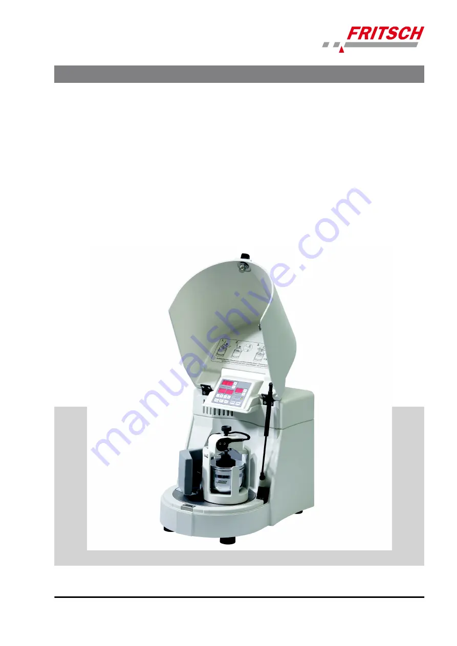
PLANETARY MONO MILL
PULVERISETTE 6 classic line
Operating instructions
Valid starting with: 06.2000/03438
Read the instructions prior to performing any task!
Translation of the original operating instructions
Page 1: ...ANETARY MONO MILL PULVERISETTE 6 classic line Operating instructions Valid starting with 06 2000 03438 Read the instructions prior to performing any task Translation of the original operating instructions ...
Page 2: ...Version 09 2020 Index 009 Fritsch GmbH Milling and Sizing Industriestraße 8 D 55743 Idar Oberstein Telephone 49 6784 70 0 Fax 49 6784 70 11 Email info fritsch de Internet www fritsch de ...
Page 3: ... GmbH An audit certified that Fritsch GmbH conforms to the requirements of the DIN EN ISO 9001 2015 The enclosed Conformity Declaration lists the guidelines the FRITSCH instrument conforms to to be able to bear the CE mark Certification CE Conformity Certifications and CE conformity 3 ...
Page 4: ...al information 17 2 8 2 Protection against restart 17 2 8 3 Overload protection 17 2 8 4 Imbalance detection 17 3 Technical data 18 3 1 Dimensions 18 3 2 Weight 18 3 3 Operating noise 18 3 4 Voltage 18 3 5 Current consumption 18 3 6 Power consumption 18 3 7 Electrical fuses 19 3 8 Material 19 3 9 Final fineness 19 4 Installation 20 4 1 Transport 20 4 2 Unpacking 20 4 3 Setting up 21 4 4 Ambient co...
Page 5: ...36 6 5 1 Clamping with the Safe Lock 5 tensioning device 36 6 5 2 Clamping the 80 ml grinding bowls 38 6 6 Mass balance 39 6 7 Grinding duration 39 6 8 Settings on the control panel 40 6 8 1 Setting the speed 40 6 8 2 Setting the running time 40 6 8 2 1 Setting time units 42 6 9 Repetition of grinding pause cycles 42 6 10 Reverse mode 43 6 11 Conducting a grinding operation 43 6 11 1 Overload 43 6...
Page 6: ...8 1 Grinding elements 54 8 2 Device 55 9 Maintenance 56 10 Repairs 58 10 1 Checklist for troubleshooting 58 11 Examples of comminution tasks 60 12 Disposal 62 13 Guarantee terms 63 14 Safety logbook 65 15 Index 67 Table of contents 6 ...
Page 7: ...dle 2 Latch 3 Hood 4 Membrane keyboard 5 Safe Lock 6 Counter weight 7 Lock 8 Bowl holder 9 Voltage rotary switch 10 Main switch 11 Mains connection 12 Circuit breaker 2x 10 A T 13 RS232 interface 14 Support disc Basic structure 7 ...
Page 8: ...e safety of the machine to carry out the required work and are able to recognize and avoid possible hazards as defined for skilled workers in IEC 364 In order to prevent hazards to users follow the instructions in this manual Malfunctions that impair the safety of persons the PULVERISETTE 6 or other material property must be rectified immediately The following information serves both the personal ...
Page 9: ...inding bowl and the lid a Rotation of the grinding bowl b Centrifugal force c Movement of the support disc 2 2 2 Drive motor and speed regulation A maintenance free three phase motor operated via a frequency con verter is used as the drive 2 3 Obligations of the operator Before using the PULVERISETTE 6 this manual is to be carefully read and understood The use of the PULVERISETTE 6 requires techni...
Page 10: ...r are in any way con nected to these The applicable accident prevention guidelines must be complied with Generally applicable legal and other obligatory regulations regarding environmental protection must be observed 2 4 Information on hazards and symbols used in this manual Safety information in this manual is designated by symbols Safety infor mation is introduced by keywords that express the ex...
Page 11: ...tances Ignoring information with this designation will result in serious or fatal injury WARNING This symbol and keyword combination points out a directly hazardous situation due to movable parts Ignoring information with this designation can result in hand injuries WARNING This symbol and keyword combination points out a directly hazardous situation due to hot surfaces Ignoring information with t...
Page 12: ...machine n Safe conduct must be strictly observed during all work n All currently applicable national and international accident preven tion guidelines must be complied with CAUTION Wear hearing protection If a noise level of 85 dB A is reached or exceeded ear protection should be worn to prevent hearing damage WARNING The maximum accepted concentration MAC levels of the relevant safety guidelines ...
Page 13: ...ICE Immediately replace damaged or illegible information signs n Unauthorised alteration of the device will void Fritsch s declaration of conformity to European directives and void the guarantee n The PULVERISETTE 6 should only be used when it is in proper working order as intended and in a safety and hazard conscious manner adhering to the operating manual In particular immediately rectify any ma...
Page 14: ...ection NOTICE Use the emergency release only if a power failure or damage to the device prevents normal opening Only open the emergency release gently and turn the trian gular key 180 degrees clockwise Any other manner of handling can damage the locking mechanism rendering the mill unusable CAUTION The emergency release must not be activated while the machine is running Disconnect the machine from...
Page 15: ...e device switches off if there is excessive imbalance If this is the case then the counterweight has to be readjusted CAUTION The imbalance switch can be disabled at your own risk The Fritsch company will give no guarantee for damage resulting from disabling of the imbalance switch NOTICE Change these settings only after all work as described in Ä Chapter 4 Installation on page 20 has been carried...
Page 16: ...he TIMER field there must be a minus sign That activates the imbalance switch and prevents a drift of the device and possible damage to the device resulting from it If the imbalance switch is deactivated a 1 is shown 5 To save and end setup mode press the STOP button 2 7 Hazardous points CAUTION Crushing hazard when closing the hood 3 Crushing hazard at the grinding bowl safe lock ten sioning devi...
Page 17: ...ainst restart In case of power failure during operation or after switching off with the main switch 10 the hood 3 is locked The hood lock 7 is opened when the power returns For safety reasons however the mill does not restart 2 8 3 Overload protection n In the event of an overload the device reduces the speed in a con trolled manner The REDUCED SPEED light is lit as a warning n The device switches...
Page 18: ...4 Voltage The device can be operated in two voltage ranges n Single phase alternating current 100 120V 10 and n Single phase alternating current 200 240V 10 See also Ä Chapter 4 5 Electrical connection on page 22 Transient overvoltage according to overvoltage category II is per mitted 3 5 Current consumption Depending on the mains voltage the maximum current consumption is in the ranges n 100 120V...
Page 19: ...e 10 A T in the frequency converter 3 8 Material n Maximum feeding size approx 10 mm n Maximum feeding amount 225 ml 3 9 Final fineness n Dry grinding up to d50 20 µm depending on the material n Wet grinding up to d50 1 µm depending on the material Technical data 19 ...
Page 20: ...nsport pallet n The pre perforated segments can be detached so that the foam parts can be removed more easily n Please store the transport packaging so that it can be reused if you need to return the product Fritsch GmbH accepts no liability for damage caused by improper packaging packaging that is not from Fritsch n Compare the contents of the delivery with your order Grinding bowls made of harde...
Page 21: ...ring oper ation Screw the two rings diagonally into the surface using the drilling template Place the 2 device feet of the mill into the intended rings n Make sure that the planetary mono mill can be easily accessed There has to be sufficient space to reach the main switch on the back side of the device n Keep the air outlet on the side ventilation grate free Risk of over heating 4 4 Ambient condi...
Page 22: ...the electrical and mechanical components Before establishing the connection compare the voltage and current values stated on the type plate with the values of the mains system to be used 1 Plug the supplied power cord into the port 11 at the back of the device 2 Then connect the device to the mains using the power cord The mains voltage has been set at the factory to that of the specific country T...
Page 23: ...y con verters are commercially available Operation without a residual current switch is possible but must be done in accordance with the relevant regu lations 4 5 1 Adjusting the mains voltage 4 5 1 1 Adjusting the mains voltage with the rotary switch 9 CAUTION Only qualified personnel may change the voltage range on the device CAUTION The voltage range may only be adjusted after the mains has bee...
Page 24: ...k side of the device and release the STOP button 3 If POWER SUPPLY is flashing the device is in setup mode If POWER SUPPLY is not flashing repeat the procedure 4 ROTATIONAL SPEED control panel area Use the ROTATIONAL SPEED buttons to adjust the level of the mains voltage 90 260 V to the existing mains system 5 To save and end setup mode press the STOP button Installation 24 ...
Page 25: ...etting device specifications NOTICE P6 must always be displayed in the REPETITIONS field The Fritsch company will give no guarantee for damage resulting from disabling of the imbalance switch Installation 25 ...
Page 26: ...tion check at a speed of 100 1 min The counterweight must be positioned completely inwards to prevent too great an imbalance n Open the hood 3 n Take out the grinding bowl tensioning device Safe Lock and trans port securing device wooden block No loose parts may remain inside the device n Position the counterweight completely inwards See Ä Chapter 6 6 Mass balance on page 39 n Close the hood 3 n S...
Page 27: ...lued into the casing with a two component construction adhe sive The adhesive is resistant to temperatures up to approx 140 C Above 140 C the adhesive will liquefy That can cause irreparable damage to the insert The grinding bowl will definitely be rendered unusable The device requires a start up phase at the beginning in order to reach maximum performance A well filled and heavy grinding set may ...
Page 28: ...teel bowl which contains iron The iron released by abrasion can com bine with sulphur and react to form iron sulphide This can lead to black deposits on your grinding set The hardness and density specific weight of the grinding bowl and grinding balls used have to be greater than that of the material used to prevent excessive wear by abrasion Material bowl and balls Main components of the material...
Page 29: ...genisation of dry or liquid samples 20 mm or smaller Homogenisation of viscous samples 20 mm These are reference values The size of bowls and grinding balls may need to be determined through experimentation NOTICE It is not advisable to mix balls of different diameters If balls with different diameters are used increased wear and damage to the grinding elements is to be expected NOTICE Balls with ...
Page 30: ... 5 15 25 30 Number of balls pcs 6 8 40 Number of balls pcs 4 Balls Ø 3mm and smaller Material Grinding bowl volume ml 80 250 500 Zirconium oxide Weight of balls gram 100 400 800 Hardened stainless steel Weight of balls gram 150 500 1100 Tungsten car bide Weight of balls gram 300 1000 2100 These are reference figures The number of balls may need to be deter mined through experimentation The minimum...
Page 31: ...0 ml agate bowl is to be filled with 1250 x 5 mm agate balls Calculation 0 17 g 1250 pcs 212 5 g 212 5 g of grinding balls can be weighed and inserted in the grinding bowl thus avoiding the time required for counting the balls 6 2 Filling quantities of grinding bowls CAUTION For wet grinding with large balls with a diameter of 10 mm at least half the maximum sample quantity must be inserted If the...
Page 32: ...0 ml 10 ml 30 ml 6 3 Filling the grinding bowl CAUTION Do not fill in any dry ice of liquid nitrogen in the grinding bowls Adding dry ice or liquid nitrogen into the grinding bowls can lead to a sudden increase in volume with a high static pressure This can result in an explosion of the grinding bowls Do not fail to comply with the following sequence 1 Place the grinding balls in the empty bowl 2 ...
Page 33: ...ase the grinding time and lower the temperature which can lead to fewer pauses This means that the overall working time may remain the same The wear is increased in this case though Fritsch recommends however to use the maximum speed and to plan for enough pauses so that the wear is minimised For thermally sensitive materials the optimal rotational speed needs to be determined through experimenta ...
Page 34: ...e replaced by smaller ball sizes during the course of the grinding process 6 4 5 Weight of the balls type of material A higher mass specific weight of the grinding balls accelerates grinding see table in Ä Chapter 6 1 Choice of grinding bowls and grinding balls on page 27 6 4 6 Dry grinding DANGER Dust explosion There is a risk of spontaneous combustion especially for very fine metal oxides and a ...
Page 35: ...each the solvent s boiling point Program appropriate cooling phases If the vapour pressure is too high vapours may escape and ignite If it can be avoided we recommend using non flammable liquids or liquids with a high boiling point The boiling point should be above100 C Achten Sie während einer Nassmahlung auf eine ausrei chende Viskosität Vor allem bei einer längeren Mahl dauer ist eine eventuell...
Page 36: ...holder The rough side should be facing upwards n Check the rubber disk in the grinding bowl holder for damage Replace the rubber disk if it has been pressed flat n The Teflon flat seal for the sealing between lid and bowl may not be damaged or soiled Replace heavily deformed Teflon flat seals n The surfaces of the lids and bowls on which the Teflon flat seals lie must be clean n Check the rubber d...
Page 37: ...amping device so that the cut out of the grinding bowl holder sits centrally in the U shaped cut out of the longer projection 5 Pre tension the setting screw e manually then place the provided torque spanner on the setting screw e and turn until it clicks 2 6 Nm Make sure that you do not turn the torque spanner too fast This could prevent the correct final clamping force from being reached Using t...
Page 38: ...stem is correctly tensioned the clamping lever is automatically pulled downwards by the eccentric when horizontal 6 5 2 Clamping the 80 ml grinding bowls There are two ways of clamping an 80 ml grinding bowl 1 Place the reducer o order no 90 1120 09 into the grinding bowl holder and position the 80ml grinding bowl on it and fasten with the Safe Lock tensioning device 2 Alternatively clamp two 80 m...
Page 39: ...r during the grinding breaks Depending on the application the grinding time should be adapted to the development of heat in the bowls The internal bowl temperature can be much higher than the outside wall temperature A guide value for the ratio of grinding time to pause time is 1 to 3 This means that if the grinding time is one minute you must allow for a 3 minute pause time If liquids are used th...
Page 40: ...g and homogenisation while monitoring the temperature Operation with an external time switch is not possible 6 8 Settings on the control panel 6 8 1 Setting the speed n Switch on the main switch 10 on the back side of the device I n The green POWER SUPPLY ready status indicator lights up on the control panel ROTATIONAL SPEED control panel area Press and hold the or button The speed can be selected...
Page 41: ...nutes seconds is set in setup mode instead of hours minutes see Ä Chapter 6 8 2 1 Setting time units on page 42 the num bers at h indicate the minutes and at min the sec onds The factory setting of the time unit is minutes and seconds Display 1 The remaining running times and the pause times are displayed during operation Operation with an external time switch is not pos sible For running times se...
Page 42: ...f POWER SUPPLY is not flashing repeat the procedure 4 To perform changes press the right button y in the TIMER field Time unit hours and minutes Display Time unit hours and minutes Display 1 factory setting 5 To save and end setup mode press the STOP button 6 9 Repetition of grinding pause cycles REPETITIONS control panel area Press or button select the number of repetitions 0 99 The number of rem...
Page 43: ...too great for example due to heavy grinding bowls the speed is reduced actual speed so that the machine is not overloaded The REDUCED SPEED lamp is lit If the mill does not start see Ä Chapter 10 Repairs on page 58 While in operation the hood 3 remains locked even during pause times and the fan cools the interior 6 11 1 Overload The device requires a start up phase at the beginning in order to rea...
Page 44: ... time switch off the main switch on the back side 6 12 Cooling the grinding bowl WARNING Burn hazard Grinding bowls can get very hot after long grinding durations Wear protective gloves for removal after grinding or during the grinding breaks n When the hood is open 3 or n In the programmed pause times with closed locked hood and the fan running 6 13 Stand by If the mill is not in operation and th...
Page 45: ...s have to be filled in a glove box with an inert gas atmosphere and closed using the additional clamping system Using this procedure you can even grind haz ardous substances 2 Grinding bowls with gassing lids can also be closed and gassed out side the device using the additional clamping system 7 1 1 Locking the additional clamping system into place 1 When using the additional clamping system exch...
Page 46: ...g system the adapter piece c 90 1120 09 provided in the accessories must be used 5 Then tighten both socket head screws d shown in the diagram equally with a hex key and thereby clamp the pressure plate tightly Ensure that the pressure plate is lying evenly on the bowl lid 6 Place the additional clamping system with clamped bowl in the grinding bowl holder Accessories 46 ...
Page 47: ...ystem for clamping 8 Position the bracket d vertically 9 Hang the longer projection of the Safe Lock clamping device into one side of the mounting of the grinding bowl holder 10 Hang the short projection of the Safe Lock clamping device into the other side Accessories 47 ...
Page 48: ...the setting screw e manually and screw it tight using the provided torque spanner Place the torque spanner provided on the setting screw b and turn until it clicks 2 6 Nm Make sure that you do not turn the torque spanner too fast This could prevent the correct final clamping force from being reached 14 Then press the clamping lever downwards 15 Wait a few seconds Release the Safe Lock again and tu...
Page 49: ...e or personal injury DANGER After several minutes of grinding and in the cooling down phases check that the tensioning device is firmly connected If the Safe Lock system is correctly tensioned the clamping lever is automatically pulled downwards by the eccentric when horizontal 7 2 Grinding in inert gas with gassing lid NOTICE Observe imbalance offsetting See Ä Chapter 6 6 Mass balance on page 39 ...
Page 50: ...bowl with grinding balls and grinding stock See Ä Chapter 6 3 Filling the grinding bowl on page 32 n Attach the Viton seal and lid n Insert the grinding bowl into the grinding bowl holder 8 n Clamp the grinding bowl in the device See Ä Chapter 6 5 Clamping the grinding bowls on page 36 Using the additional clamping system the following steps can also be completed in the glove box and subsequently ...
Page 51: ... the device when both coupling and ven tilation attachment have been removed Overpressure may occur during grinding 7 2 3 Ventilate after grinding CAUTION Always let the bowl cool down before ventilation Hot gases and sample material may escape from the bowl during pressure equalisation leading to serious burns Use protective gloves when ventilating n When the bowl has cooled down remove the addit...
Page 52: ...e the lid 7 2 5 Installing valve inserts n Insert the valve insert g into the valve d with the spring pointing upwards n With the valve screwdriver f screw the valve insert clockwise The following gassing lids for the grinding sets are available each with two valves and a soft sealing ring Material Order number Hardmetal tungsten carbide 80 ml 50 8880 00 Hardmetal tungsten carbide 250 ml 50 8600 0...
Page 53: ...t most NOTICE The grinding parts made of agate are only designed for temperatures of up to 100 C After this point they need to be slowly and carefully cooled down 7 3 GTM system The GTM system is available as an accessory for recording pressure and temperatures in the grinding bowl during grinding Instructions are included with the GTM system Accessories 53 ...
Page 54: ...ts made of agate sintered corundum zirconium oxide and silicon nitride slowly and carefully Do not heat agate elements in a microwave under any circumstances heating is too fast They must never be exposed to thermal shocks as this could cause irreparable damage to the parts They will burst apart like in an explosion n Clean the grinding bowl and grinding balls each time after using them Clean them...
Page 55: ...8 2 Device n The planetary mill can be wiped down with a damp cloth when it is switched off Cleaning 55 ...
Page 56: ... costs of this maintenance itself We recommend keeping a safety logbook Ä Chapter 14 Safety logbook on page 65 where all work mainte nance repairs performed on the device is entered The most important element of maintenance is regular cleaning Functional part Task or description Test Maintenance interval Safety lock Hood lock 7 Is the closed hood 3 locked in place when the main switch is off If th...
Page 57: ...replace if pressed flat and no longer elastic After every 1 000 h Indicated surfaces of Safe Lock are round Original height 12 5 mm Minimum height 12 mm y Safe Lock has frequently been tensioned too loosely After every 200 h If the height is under the minimum height the corre sponding part has to be replaced Grinding bowl lid seal Seal the grinding bowl Replace seal if dirt has penetrated After ev...
Page 58: ... page 20 Pause time active Wait for end of pause or press STOP Safety lock 7 was opened man ually See Ä Chapter 2 6 1 Opening the hood without mains connection on page 14 Mill reduces speed automati cally If REDUCED SPEED is lit Overload Reduce load or accept automatically set speed Mill stops running Switched off due to thermal over load of the drive Allow device to cool down and select a lower s...
Page 59: ...of device 2 x 10 A T 12 Grinding stock escapes Tensioning device 5 loose Check and re tension if necessary Seal ring is soiled or defective Clean or replace seal ring Runs unevenly with strong vibrations Masses balanced inadequately Set mass balance more adequately See Ä Chapter 6 6 Mass balance on page 39 Repairs 59 ...
Page 60: ...water 40 g 50 ml water Cr Ni steel 6 x 30 mm 100 2 mm 250 ml 60 min 10 µm Coal dry and wet grinding in water 5 g Zirconium oxide 5 x 20 mm 100 0 5 mm 80 ml 120 min 15 µm Aluminium oxide silicon oxide 100 g WC Co 15 x 20 mm 90 0 1 mm 250 ml 90 min 20 µm Ferrovanadium 70 g WC Co 5 x 30 mm 70 3 mm 250 ml 20 min 100 µm Glass 50 g Agate 15 x 20 mm 100 4 mm 250 ml 15 min 90 µm Silicon carbide dry and we...
Page 61: ...er 150 ml Cr Ni steel 15 x 20 mm 100 0 025 mm 250 ml 30 min 5 µm Plaster 300 g Cr steel 10 x 30 mm 100 10 mm 500 ml 20 min 200 µm Protein 50 g Sintered corundum 1 6 x 30 mm 90 20 mm 250 ml 90 min 50 µm Grains barley 100 g Sintered corundum 1 3 x 40 mm 100 3 mm 500 ml 20 min 150 µm Dough products 100 g Sintered corundum 1 10 x 30 mm 100 5 mm 500 ml 3 min 250 µm Sugar wet grinding in alcohol 200 g A...
Page 62: ... Analytical devices have been registered under category 9 monitoring and control instruments It has been accepted that FRITSCH is operating only in the business to business area The German registration number for FRITSCH is WEEE reg no DE 60198769 FRITSCH WEEE coverage Since the registration of FRITSCH is classified for bilateral transactions no legal recycling or disposal process is described FRI...
Page 63: ...receipt of the device and be received by us within three weeks or alternatively online registration must be car ried out with the above mentioned information The guarantee will not be granted in cases where n Damage has arisen due to normal wear and tear especially for wear parts such as Crushing jaws support walls grinding bowls grinding balls sieve plates brush strips grinding sets grinding disk...
Page 64: ...nt to remedy all recognisable errors or faults including those not covered by the guarantee Errors or faults not covered by the guarantee shall in this case be rectified at cost We recommend reading the operating manual before contacting us or your dealer in order to avoid unnecessary inconvenience Ownership of defective parts is transferred to us with the delivery of the replacement part the defe...
Page 65: ...14 Safety logbook Date Maintenance Repair Name Signature Safety logbook 65 ...
Page 66: ...Date Maintenance Repair Name Signature Safety logbook 66 ...
Page 67: ...y 19 Examples of comminution tasks 60 Explanation of signs 10 Explanation of symbols 10 F Filling quantity of grinding bowls 31 Final fineness 19 G Grinding balls Selecting 27 Grinding bowl Filling 32 Selecting 27 Grinding in inert gas 49 Grinding time 33 39 GTM system 53 Guarantee terms 63 H Hazardous points 16 I Initial start up 26 Installing valve inserts 52 M Maintenance 56 Material 19 N Numbe...
Page 68: ...ty logbook 65 66 Scope of application 8 Setting the grinding duration 40 Setting the speed 40 Setting up 21 Size of the grinding balls 29 Skilled workers 8 Stand By Mode 44 T Troubleshooting checklist 58 U Unpacking 20 Unwuchterkennung 17 V Ventilating after grinding 51 Voltage 18 W Warning information 10 WEEE 62 Weight 18 Wet grinding 35 Index 68 ...
Page 69: ......
Page 70: ... 2014 Fritsch GmbH Milling and Sizing Industriestraße 8 D 55743 Idar Oberstein Telephone 49 6784 70 0 Fax 49 6784 70 11 Email info fritsch de Internet www fritsch de ...