S70-101SM
Page 12
Frick XJS and XJF Rotary Screw Compressor
Service Manual
1.2.1 JACKSHAFT AND GEARS – REMOVAL. (CONTD)
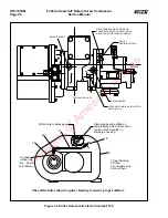
14. If necessary, remove inner race of roller bearing (11) from
jackshaft using Bearing Inner Race Puller (Owattona Tool Co.
p/n 1123).
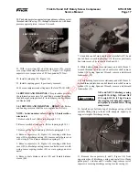
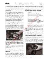
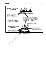
6. Install retaining ring (12) in gear cover (52).
Ensure that tool is against outer
race and not against cage and bear-
ing rollers.
7. Install outer race of roller bearing (11) in gear cover.
Bearing can be installed by freezing and installing it in gear
cover or by using Discharge Ball Bearing Installation Tool
and rubber mallet. Ensure that roller bearing is tight against
retaining ring (12).
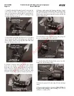
8. Slide jackshaft and gear set assembly (14) into gear cover
until inner race of roller bearing is seated under the rollers
of inner race bearing.
9. Using Jackshaft Bearing Installation Tool, press inboard
half of four-point contact ball bearing (9) inner race against
inner race of roller bearing (11).
DISCHARGE
BALL BEARING
INSTALLATION TOOL
JACKSHAFT AND GEAR
ASSEMBLY
JACKSHAFT BEARING
INSTALLATION TOOL
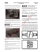
5. Heat inner race of roller bearing (11) to 250
O
F (121
O
C) for
one hour, and install race on jackshaft. Push inner race against
bearing spacer (13) and hold in place until bearing cools and
grips jackshaft.
Protective, heat-resistant gloves
must be worn when installing bear-
ing inner race.
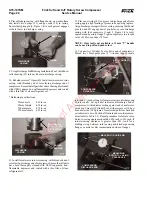
3. Heat inner race of roller bearing (17) to
250×
F (232
×
C) for one
hour, and install race on jackshaft. Push inner race against bearing
spacer (16) and hold in place until race cools and grips jackshaft.
4. Install outer race of bearing (17) in rotor casing (22); secure
with retaining ring (15).
Protective, heat-resistant gloves
must be worn when installing bear-
ing inner race.
15. If necessary, remove inner race of roller bearing (17) from
jackshaft using Bearing Inner Race Puller.
16. Remove bearing spacer (16) from jackshaft.
17. Remove retaining ring (15) and outer race of roller bearing
(17) from rotor casing (22).
1.2.2 JACKSHAFT AND GEARS – INSTALLATION.
Jackshaft and gears installation shall be accomplished as follows:
NOTE: Index numbers refer to Figure 1-2, unless other-
wise noted.
1. Thoroughly clean all parts with OSHA approved, nonflam-
mable degreaser and clean, lint-free rags.
NOTE: If replacement Jackshaft Kit is used, steps 2
through 5 do not apply.
NOTE: In preparation for installing pinion gear in
step 12 heat gear to maximum 450
O
F (121
O
C) for approxi-
mately three hours..
2. Install bearing spacer (16) onto jackshaft (1) against main
gear (14).
CAUTION
WARNING
WARNING
Property of American Airlines


