S70-101SM
Page 22
Frick XJS and XJF Rotary Screw Compressor
Service Manual
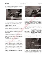
32. Install modified Female Distance Sleeve Tool (female
distance sleeve with center hole drilled out to
5
/
8
-inch) over
female rotor shaft and thread 5
1
/
2
-inch guide pin into end of
shaft. Install modified Outlet Bore Cover Tool (part of
Discharge Ball Bearing Removal Tool) with wave spring
(42) on discharge casing; secure with capscrews (8, Figure
1-4). Tighten capscrews to a torque value of 18 foot-pounds
(24.5 Nm).
33. With Air Cylinder Tool still attached to drive end of
compressor and using regulator to restrict air pressure to 35
psi max., take same measurements as in step 13, this section.
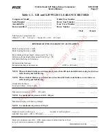
With bearing clamped, record female rotor “measured” end
play in Table 1.1 for future reference.
34. Remove modified Female Distance Sleeve Tool, guide
pin, and modified Outlet Bore Cover Tool from female rotor.
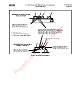
35. Install compression springs (37) in outlet bore cover
(39). Install new o-ring (27) on cover. Install male distance
sleeve (38), with spring pin hole at 12 o’clock position in
outlet bore cover; secure with capscrews (8, Figure 1-4).
Tighten capscrews to a torque value of 18 foot-pounds (24.5
Nm). Ensure that spring pin (9, Figure 1-4) in cover
engages hole in male distance sleeve.
36. Install new o-ring (27) in outlet bore cover (41). Install
female distance sleeve (44), with roll pin hole at 7 o’clock
position, wave spring (42), and outlet bore cover; secure
with capscrews (8, Figure 1-4). Tighten capscrews to a
torque value of 18 foot-pounds (24.5 Nm). Ensure that
spring pin (40) in cover engages hole in female distance
sleeve.
37. Install slide valve and slide stop. (Refer to paragraph 1.3.2.)
38. Install jackshaft and gears. (Refer to paragraph 1.2.2.)
39. Install shaft seal. (Refer to paragraph 1.1.2.)
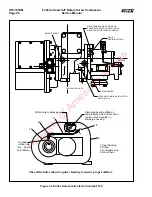
With bearing clamped, record male rotor “measured” end
play in Table 1.1 for future reference (should be within
.0015" - .003".
31. Remove modified Male Distance Sleeve Tool, guide pin,
and modified Outlet Bore Cover Tool from male rotor.
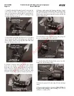
28. Install lockwasher (35) and locknut (36) on male rotor
shaft; tighten locknut with spanner wrench. Bend one tab of
lockwasher on end of male rotor shaft into one of the recesses
of locknut. This secures locknut in place and prevents it from
turning on rotor shaft.
29. Install modified Male Distance Sleeve Tool (male dis-
tance sleeve with center hole drilled out to
5
/
8
-inch) over male
rotor shaft and thread 3
1
/
2
-inch guide pin into end of shaft.
Install modified Outlet Bore Cover Tool (part of Discharge
Ball Bearing Removal Tool) with compression springs (37)
on discharge casing; secure with capscrews (8, Figure 1-4).
Tighten capscrews to a torque value of 18 foot-pounds (24.5
Nm).
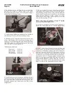
30. With Air Cylinder Tool still attached to drive end of
compressor and using regulator to restrict air pressure to 35
psi max., take same measurements as in step 13, this section.
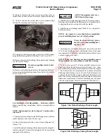
COMPRESSOR
DISCHARGE END
OUTBOARD HALF
(INNER RACE)
1.4.2 ROTORS AND BEARINGS – INSTALLATION. (CONTD)
outboard half of inner race of four-point contact ball bearing
on male rotor shaft.
INBOARD HALF
(INNER RACE)
DISCHARGE
BALL BEARING
INSTALLATION TOOL
26. Install outer race of four-point contact ball bearing (34) on
male rotor shaft.
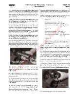
27. Using Discharge Ball Bearing Installation Tool, install
25. Using Discharge Ball Bearing Installation Tool, install
inboard half of inner race of four-point contact ball bearing
(34) on male rotor shaft.
OUTLET BORE COVER
TOOL
CHECKING MALE ROTOR
“MEASURED” END PLAY
Property of American Airlines


