S70-101SM
Page 19
Frick XJS and XJF Rotary Screw Compressor
Service Manual
20. Remove female rotor from rotor casing. Place rotor on
cardboard or wooden surface. Rotor may require rebalancing.
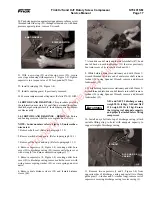
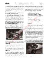
21. At drive end of rotor casing, remove two retaining rings
(50 and 18) securing roller bearings in place.
ROLLER BEARING
PULLER
ROTOR CASING
DRIVE END
22. From drive end of rotor casing, remove two roller bearings
using Roller Bearing Puller (Owattona Tool Co. p/n 943).
23. Remove female inlet bushing (48) and male inlet bushing
(21) from rotor casing.
Do not use open flame torch to heat
rotors.
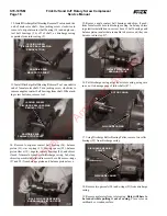
24. Remove roller bearing inner races from male and female
rotors, using Roller Bearing Inner Race Puller (Owattona
Tool Co. p/n 1123).
1.4.2 ROTORS AND BEARINGS – INSTALLATION.
Rotors and bearings installation shall be accomplished as
follows:
NOTE: Index numbers refer to Figure 1-2, unless other-
wise noted.
1. Thoroughly clean all parts with OSHA approved, nonflam-
mable degreaser and clean, lint-free rags.
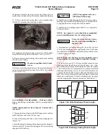
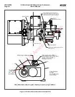
2. Lube all internal parts with a coat of clean refrigerant oil
(Figure 1-8).
3. Install female inlet bushing (48) and male inlet bushing (21)
in rotor casing (22). Ensure that spring pin (20) in rotor casing
engages hole in bushing.
Protective, heat-resistant gloves
must be worn when installing bear-
ing inner race.
ALWAYS tap against outer race –
NEVER on ball and cage.
4. Install two new roller bearings (49 and 19) in rotor casing.
Bearings can be installed by freezing prior to installation or
by tapping them into casing with a rubber mallet.
5. Install two new retaining rings (50 and 18), securing roller
bearings in place.
NOTE:
Any repair to rotors should be accomplished
prior to installing inner races of roller bearings.
6. Heat inner races of roller bearings (25, 49, and 19) to 250
×
F
(121
×
C) and install onto male and female rotors. Push inner
races against shaft shoulders and hold in place until inner race
cools and grips rotor shaft.
NOTE:
When new bearings are being installed, ensure
that each inner race is matched to respective bearing.
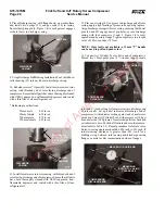
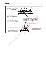
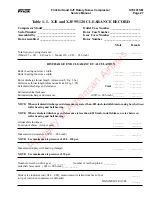
7. If a new rotor pair (47) is being installed, measure rotor
discharge throat length on each rotor (Figure 1-5a). Also,
measure discharge casing throat length for each rotor (Figure
1-5b). Subtract the two measurements to obtain calculated
discharge end clearance for each rotor. End clearances for
each rotor should be .0015- inch to .003-inch (.038 mm to .076
mm). If necessary, shims must be added in step 14 to meet this
dimension requirement. Calculate discharge end clearance
and select appropriate shims in accordance with Table 1.1.
Figure 1-5b. Discharge Casing Throat Length.
Figure 1-5a. Rotor Discharge Throat Length.
R
S
M
F
8
WARNING
CAUTION
CAUTION
Property of American Airlines


