S70-101SM
Page 13
Frick XJS and XJF Rotary Screw Compressor
Service Manual
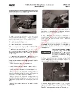
10. Press outer race of four-point bearing into gear cover,
using seal housing (4); remove seal housing.
11. Using Jackshaft Bearing Installation Tool , press outboard
half of four-point contact ball bearing (9) inner race in place.
Protective, heat-resistant gloves
must be worn when installing bear-
ing inner race.
DO NOT force pinion gear into po-
sition. If pinion gear does not seat
properly on first attempt, remove,
reheat, and reinstall.
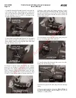
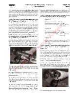
12. Install heated pinion gear on male rotor shaft (17). Push
pinion gear against shaft shoulder; hold in place until gear
cools and grips jackshaft.
PINION GEAR
13. Lubricate all internal compressor parts with a thin coat of
clean refrigerant oil.
NOTE: If 12mm guide pins were taken out after gear
cover was removed, reinstall pins in opposite sides of
casing, to facilitate cover installation.
14. Install new o-ring (51) in drive-end of rotor casing; use a
light coating of grease to hold o-ring place
It is important that jackshaft ro-
tates when cover is installed. If shaft
does not rotate, it may be binding
in roller bearing.
15. Install the gear cover and secure in place with capscrews
(7); tighten capscrews to a torque value of 58 foot-pounds (79
Nm). Remove guide pins.
Protective, heat-resistant gloves
must be worn when installing glyd-
ring.
Place section of shim material on in-
side of hose clamp to prevent pos-
sible damage caused by clamp holes.
16. If previously removed, install o-ring (11, Figure 1-4) and
glyd-ring (10, Figure 1-4) on slide stop piston (26, Figure 1-
4). To install glyd-ring, heat to 250
×
F (121
×
C) for one hour
and push into slot. Use a 4-inch (10 cm) hose clamp to hold
glyd-ring in place for 10 minutes.
Protective, heat-resistant gloves
must be worn when installing bear-
ing inner race.
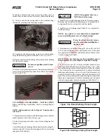
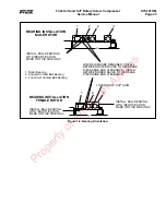
18. Place slide stop piston inside stepper piston. Thread 8mm
T-wrench into stepper piston; install stepper piston and slide
stop piston in compressor.
STEPPER PISTON
8MM T-WRENCH
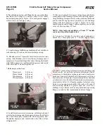
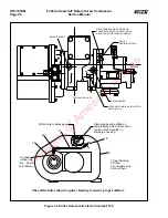
19. Push stepper piston against spring force and remove 8mm
screw previously threaded into slide stop through drain hole;
keep hand pressure against piston and remove T-wrench.
20. Position slide stop cover (30, Figure 1-4), with new o-ring
(32, Figure 1-4) on gear housing (2, Figure 1-4); secure slide
stop cover to gear housing with capscrews (1). Tighten
capscrews to a torque value of 58 foot-pounds (79 Nm).
21. Install compressor drain plug (24, Figure 1-4).
22. Install flexible drive coupling. (Refer to S70-101 IOM.)
23. Evacuate compressor and oil separator. (Refer to S70-101
IOM.)
1.3 SLIDE VALVE AND SLIDE STOP. This procedure
provides the information necessary for qualified personnel to
replace the slide valve piston glyd-rings, including required
compressor disassembly.
1.3.1 SLIDE VALVE AND SLIDE STOP – REMOVAL.
Slide valve and slide stop removal shall be accomplished as
follows:
NOTE:
Index numbers refer to Figure 1-4, unless other
wise noted.
1. Evacuate compressor and oil separator. (Refer to S70-101
IOM.)
2. Remove coupling guard, if necessary.
3. Place suitable drain pan under compressor and remove oil
drain plug (24).
There is spring force behind slide
stop cover. Hold stepper piston (27)
in by hand.
WARNING
CAUTION
CAUTION
CAUTION
WARNING
WARNING
CAUTION
Property of American Airlines


