


140.960-IOM (JUN 2016)
Page 39
IDCF & IDC3 EVAPORATIVE CONDENSERS
OPERATION
NOTICE
The minimum turndown ratio for units with a belt drive
is 10:1 (or 6 hz). Units with the oil pump do not have a
minimum speed.
• Please refer to the manufacturer’s variable frequency drive
recommended start-up procedure for further information
or consult with your Frick sales representative for any VFD
applications.
RESONANT SPEED IDENTIFICATION PROCEDURE
There are several characteristic frequencies at which vibration
levels may resonate with unit structural components. These
include fan speed, motor speed, bearing frequency, and blade
pass frequency.
Within the overall operating speed range of a unit, it is not
unusual for one or more of these characteristic frequencies
to excite the structural components over relatively small
speed ranges and create an increase in vibration levels. If the
vibration levels are excessive at these resonant speeds, they
need to be locked out to prevent the VFD from operating the
motor at these speeds. The following procedure describes
how to identify the lockout speed ranges:
NOTICE
The resonant speed identification procedure must be per-
formed at start-up for units with VFDs.
• Ensure the VFD that controls the fan motor is off, and the
power to the motor circuit is locked out.
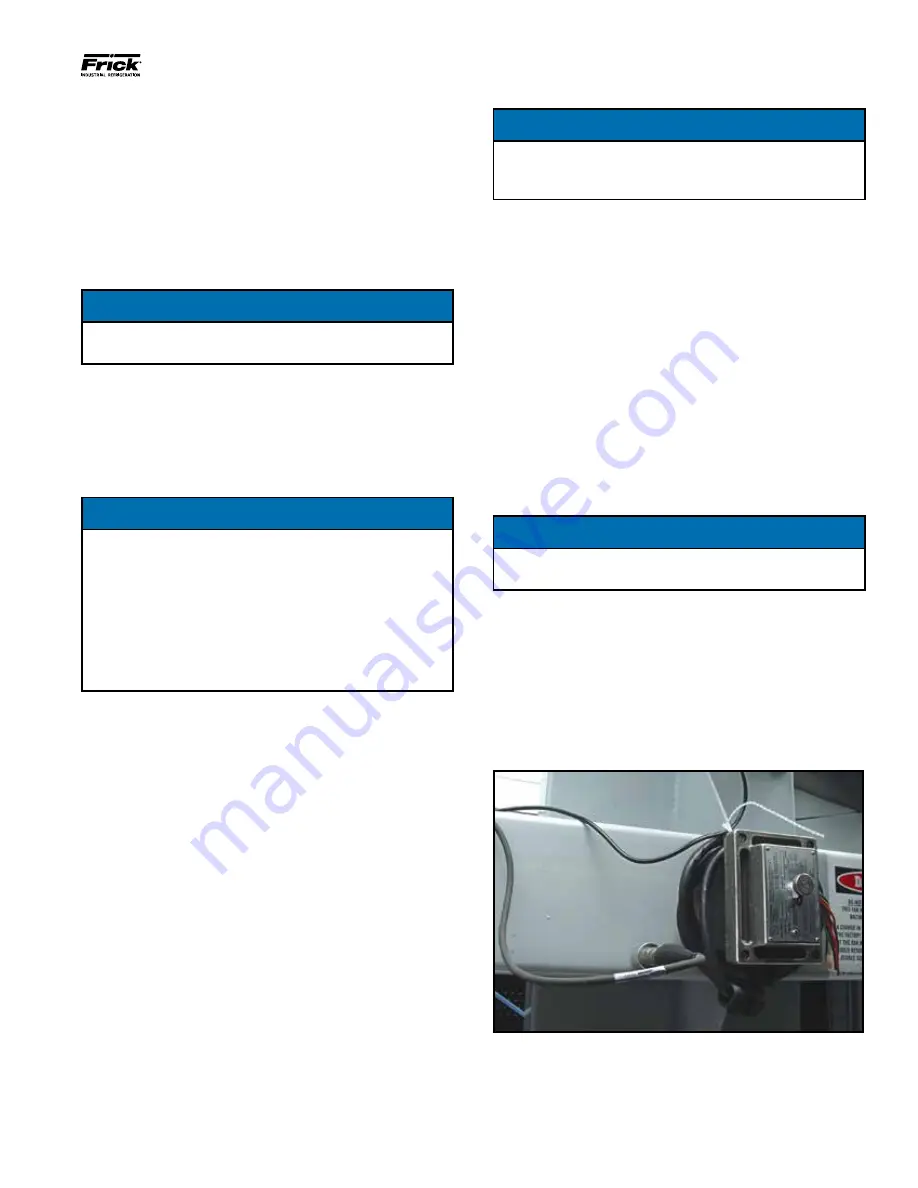
•
Attach the accelerometer (provided by
others) onto the box beam as shown in
Figure 10. The accelerometer should be located away
from the center of the web of the box beam, such that the
center line of the accelerometer is about 1 inch from the
upper or lower edge, as shown. On IDCF/IDC3-0406 and
-0412 units, the accelerometer should be located directly
on the motor base.
Figure 55 – Accelerometer Location - Belt Drive
INDEPENDENT FAN CONTROL (OPTIONAL)
Independent fan control is standard on 0412 and 0718 units
and optional on 1218, 2418, and 2436 units.
In an operating induced draft unit with independent fan
capabilities and no partitions, idle fans tend to windmill in the
reverse direction. A windmilling fan poses no threat to the
system while turning freely, but can create a large shock load
when the fan motor is suddenly powered up. Proper staging
of fans when starting from a windmilling condition will prevent
excessive stresses on the drive system.
NOTICE
With evaporative cooling, a 15 second fan motor delay will
not be noticed when staging up.
There are two control strategy options:
VFD
The recommended control option is to use a variable
frequency drive to control all of the motors. VFDs regulate
motor speed electronically and start motors with reduced
voltage and frequency. The result is a gentle motor start, and
therefore reduced stress.
NOTICE
For a unit with a VFD, with a switching frequency of 2.5
kHz, the line lead length cannot exceed 100 feet. If the
switching frequency is higher that 2.5 kHz and/or the line
lead length exceeds 100 feet, a dV/dT output filter is rec-
ommended to protect the motor.
Since the switching frequency and maximum line length
requirements vary between VFD and motor suppliers,
contact your Frick sales representative to determine if a
dV/dT filter is required.
No VFD
• Staging Up: Turn all motors off for 15 seconds. Following
the 15 second delay, bring all required fans online. Allow
for a 1 second time delay between fan stages to reduce
staging current.
• Staging Down: Turn off the fan motor. No need for delays.
VARIABLE FREQUENCY DRIVE
• Applications utilizing variable frequency drives (VFDs) for
fan motor control must use inverter duty motors built in
compliance with NEMA standard MG-1, Part 31.
• Operation of the unit at a speed which resonates with
components of the drive system or support structure may
result in vibrations which could damage the components
or structure, and/or create objectionable noise. Therefore,
these resonant speed ranges should be identified at start-
up and locked out to prevent operation of the motor at
these resonant speeds. Conduct the following “Resonant
Speed Identification Procedure."


