


HPS Rotary Screw Compressor Units
070.700-IOM (MAR 21)
Page 32
Maintenance
Notice
Evacuation of the oil separator assists the flow of oil
into the unit. Also, fill slowly because oil fills up in
the separator faster than it shows in the sight glass.
for approximate oil charge quantities.
12.
Open the suction and discharge service valves, and
also the liquid injection and economizer service valves,
if applicable.
13. Close the disconnect switch for the compressor motor
starter.
14. Start the unit.
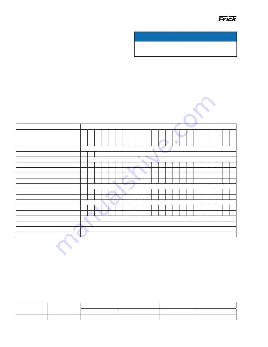
Maintenance schedule
Follow this schedule to ensure trouble-free operation of the compressor unit.
8. Remove, clean, and reinstall the strainer elements in
the strainers.
9.
Evacuate the unit to 29.88 in.Hg (1000 microns)
vacuum.
10. Open the suction service valve and pressurize the unit
to system suction pressure. Close the suction valve and
leak test.
11.
Add oil by attaching a suitable pressure-type hose to
the
oil drain valve located under the separator. Using a
pressure-type oil pump and appropriate Frick
oil, open
the drain valve and fill the separator until the oil level is
midway in the top
sight glass.
HPS package
model
Compressor
model
Discharge flange to separator flange
Compressor suction flange
Bolt size (mm)
Torque, ft-lb (N⋅m)
Bolt size (mm)
Torque, ft-lb (N⋅m)
HPS 36, 42, 60
HPSH 1510
M20 X 2.5
250 (339)
M22 X 2.5
150 (203.4)
Note
: For discharge flange to separator flange torque, based on Gaskets-Garlock
®
Blue-Gard
®
3300. Bolts-class 8.8 or stronger hex head
bolts, lightly oiled and clean
Table 10: Bolt sizes and torque
Frequency or hours of operation (maximum)
Maintenance
200
1000
5000
8000
10
,000
15
,000
20
,000
25
,000
30
,000
35
,000
40
,000
45
,000
50
,000
55
,000
60
,000
65
,000
70
,000
75
,000
80
,000
85
,000
90
,000
95
,000
Change oil
As directed by oil analysis
Oil analysis
n
Every 6 months
Replace oil filters
n
As directed by oil analysis
Clean oil strainers
n
n
n
n
n
n
n
n
n
n
n
Clean liquid strainers
n
n
n
n
n
n
n
n
n
n
n
Replace coalescers
n
n
n
Check and clean suction strainer
n
n
n
n
n
n
n
n
n
n
n
Check coupling
n
Annually regardless of operating hours
Check alignment
n
n
n
n
n
n
n
n
n
n
n
Suction and discharge flange bolts
n n n n n n n n n n n n n n n n n n n n n n
VFD units check skip freq.
Check annually
Check electrical connections
n
n
n n n n n n n n n n n n n n n n n n
Check sensor calibration
n n n
n n n n n n n n n n n n n n n n n n
Test high pressure cut-out
Test annually
Vibration analysis
Every 6 months, more frequently if levels increase
Motor grease
See motor grease section. Follow motor manufacturer's recommendation
Replace shaft seal
When leak rate exceeds 7 to 8 drops a minute
Notes:
•
For Check coupling, check bolts, shim packs, center inserts, keys, and all bolt torques.
•
For Suction and discharge flange bolts, verify the tightness of the bolts. See
for torque requirements.
•
For variable frequency drive (VFD) units, check for excess vibration and skip frequencies any time unit operating conditions change.
•
For Check electrical connections, check and torque all terminals in the processor and starter panel as shown in the specification posted in
the enclosure.
• For Check senor calibration, check the calibration of the slide valve, slide stop, pressures and temperatures. Conduct calibration with
NIST- certified devices.
•
For Vibration analysis, baseline vibration analysis is required during initial commissioning. Vibration measurement must be carried out con
-
tinuously to obtain optimum preventive control on bearings. If not continuously controlled, then every 6 months, more frequently if levels
increase. See additional notes in
•
For Replace oil filters, the filter may need to be changed more frequently based on differential pressure or as directed by oil analysis.
•
For Check alignment, refer to
070.210-IB, Screw Compressor Foundations
for foot-mounting alignment.