Frick AGBF Installation Operation & Maintenance Download Page 9

610.020-IOM (NOV 19)

Page 9

EVAPORATOR AND AIR COOLER

INSTALLATION - OPERATION - MAINTENANCE

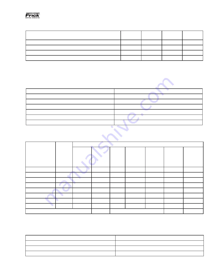
Table 3: Defrost types based on room temperature

Temperature 

Air 
defrost

Water 
defrost

Electric 
defrost

Hot gas 
defrost

High temperature > 40°F (4.4°C)

Yes

No

No

No

Medium temperature > 20°F (-6.7°C) < 40°F (4.4°C)

No

Yes

Yes

Yes

Low temperature < 20°F (-6.7°C)

No

Yes

Yes

Yes

Ultra low temperature < -40°F (-40°C)

No

No

Yes

Yes

Note:

 Insulated pans are recommended for any application with a room temperature below freezing.

Table 4: Hot gas pressures at the evaporator

Refrigerant

Required pressure at evaporator, psig (bar)

R22

90 to 110 (~6 to 7.5)

R404a

115 to 140 (~8 to 9.5)

R507A

115 to 140 (~8 to 9.5)

R134a

50 to 65 (~3.5 to 4.5)

R410a

155 to 185 (~10.5 to 12.5)

NH

3

80 to 100 (~5.5 to 7)

Table 5: Hot gas defrost - sequence of operation

Defrost stages

Time in 
minutes 
(approx.)

Control Valves

Liquid  
solenoid 
(LSV)

Suction 
solenoid 
(SSV)

Delay

Soft hot 
gas sole-
noid valve 
(SHGSV)

Hot gas 
solenoid 
valve 
(HGSV)

Bleed sole-
noid valve 
(BSV)

Fan motor/
motors 
running

Refrigeration mode xx

yes

Pump out period

10 - 30

yes

Delay

5 s - 10 s

no

Soft gas period

1 - 2

no

Hot gas period

5 - 30

no

Equalizing period

2 - 5

no

Fan delay period

1 - 3

no

Refrigeration mode xx

yes

=

Solenoid open

Table 6: Wattages for electric defrost

Temperature range

Wattage per ft

2

 of coil surface area

Medium temperature > 20°F (-6.7°C) < 40°F (4.4°C)

6 to 8

Low temperature < 20°F (-6.7°C)

8 to 12

Ultra low temperature < -40°F (-40°C)

12 to 15

Summary of Contents for AGBF

Page 1: ...s may result in personal injury or death damage to the unit or improper operation EVAPORATORS AND AIR COOLERS AGHN AXGHN MANP MXANP MDAN MDXAN AGBF GHN MDN and GGHN Check www FrickCold com for the lat...

Page 2: ...rmation Safety instructions 3 Refrigerant safety 3 General information Warranty statement 3 Product lines 4 Installation Receiving and inspection 5 Air cooler location 5 Air cooler mounting 5 Operatio...

Page 3: ...f approximately 15 to 28 by volume in air When mixed with lubricating oils its flammable concentration range is increased It can explode if re leased in an enclosed space with a source of ignition pre...

Page 4: ...buyer return postage and freight paid This shall constitute full compliance with FRICK s warranty obliga tions hereunder FRICK accepts no liability for the direct or indirect consequences of any modi...

Page 5: ...ce of the air inlet side of the coil from the wall is at least 0 8 x face height to prevent obstructed air flow patterns The face height is the height of the evapo rator coil without the frame Positio...

Page 6: ...pressor overloads Check drain pan for proper drainage Check thermostatic expansion valves for proper super heat settings Adjust all adjustable controls and valves in the field to meet required operati...

Page 7: ...ing dimensions on industry accepted good engineering design principles For direct expansion units select expansion valves in ac cordance with selection data and as required by expansion valve manufact...

Page 8: ...not reverse cycle Incorporate a soft start hot gas solenoid valve in the valve station into evaporators with capacities greater than 15 tons 52 kW This valve allows the coil to ease up to the hot gas...

Page 9: ...4a 115 to 140 8 to 9 5 R507A 115 to 140 8 to 9 5 R134a 50 to 65 3 5 to 4 5 R410a 155 to 185 10 5 to 12 5 NH3 80 to 100 5 5 to 7 Table 5 Hot gas defrost sequence of operation Defrost stages Time in min...

Page 10: ...too low All water lines within refrigerated spaces must be insu lated and heat traced to prevent these lines freezing Lines must also be pitched up to 1 2 in per linear ft to allow the water to drain...

Page 11: ...ree space of at least the length of the unit on the electric connection side to remove the heaters in case of failure 5 Dimensions B and C can be reduced to minimum of 6 in on the refrigerant connecti...

Page 12: ...N GGHN MHF 071 Step 1 When shipped units are stacked but individually skidded Step 2 Separate the top unit from the lower unit Step 3 Remove all crating from the top and sides of the skid Leave the un...

Page 13: ...and Step 1 Units shipped with heavy duty plastic wrap on the skid Step 2 Remove plastic wrap and support members from the unit Step 3 Leave the unit on the skid and place forks under the full span of...

Page 14: ...Step 1 As shipped units are stacked but individually skidded Step 2 Remove all crating from the top and sides of the skids Leave the units on the skids Step 3 Place forks under the full span of the sk...

Page 15: ...nd shipping supports b If unit is foot mounted remove the skid Or If unit is ceiling hung leave the skid in place and secure the hangers to support rods d Remove skid Step 4 a Use a spreader bar when...

Page 16: ...Step 1 Units shipped with heavy duty plastic wrap on the skid Step 2 Remove plastic wrap and support members from the unit Step 3 Leave the unit positioned on the skid Place forks under the full span...

Page 17: ...MBK AGBK MGBK Step 1 Units are shipped stacked but individually skidded Step 2 Remove all crating from the top and sides of skids Leave units on skids Step 3 Place forks under the full span of the sk...

Page 18: ...ans operate silently General state of the unit such as cleanliness and corro sion Cleaning the finned heat exchanger is of particular im portance to ensure smooth operation and long life of the equipm...

Page 19: ...correctly Adjust setting for fan delay duration CLEANING WARNING All power must be disconnected and locked out before any cleaning The drain pan also serves as a cover for hazardous moving parts Oper...

Page 20: ...Defective heater element or elements Replace element or elements Unit incorrectly pitched Check and adjust accordingly Condensate drain line plugged Clean drain line Defective drain line heater Replac...

Page 21: ...610 020 IOM NOV 19 Page 21 EVAPORATOR AND AIR COOLER INSTALLATION OPERATION MAINTENANCE NOTES...

Page 22: ...ynesboro PA 17268 1206 USA Phone 717 762 2121 FAX 717 762 8624 www johnsoncontrols com FRICK Form 610 020 IOM 2019 11 Supersedes NOTHING Subject to change without notice Published in USA 11 19 PDF 201...

Reviews: