


Interface Description
MPC5604P Controller Board User’s Guide, Rev. 0
Freescale
9
The controller board is powered from two independent voltage regulators which provides 5V for a
auxiliary logic and 5V for MCU and debugger logic. Both voltages are generated by the MC33905 SBC
integrated circuit. Proper operation is monitored by LED D114 for the AUX 3.3V line, see
Table 2
.
The board is designed to operate in the voltage range from 8V to 18V. The board is protected against a
reverse battery.
3.2
UNI3 Interface J300
The UNI-3 interface (connector J300) defines the interface between the MPC5604P Controller Board and
a 3 phase electrical motor power stages.
The list of UNI-3 signals follows:
•
Control signals:
— PWM phase A, B, C top and bottom switches control
— Brake signal control
— Power Factor Correction (PFC)
•
Monitor signals
— DC-bus voltage
— DC-bus current
— Phase A, B, C current
— Zero-cross signals
— Back-EMF phase A, B, C
— Temperature monitoring
•
Power Supply 12V
•
Serial line - a bidirectional communication line between the Controller Board and Power Stage
The
Table 3
defines the UNI-3 pin-out and pin assignment to the MCU.
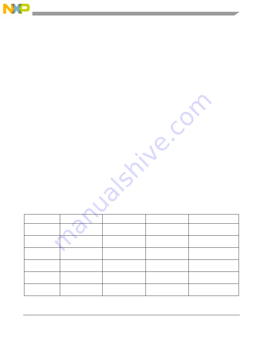
Table 3. Motor 1 - UNI-3 Signal Description
Interface Pin
Signal Name
MCU Signal
Description
Direction
1
PWM_AT
PWM_A0
Phase A top switch
control (H -> Turn OFF)
Digital output
3
PWM_AB
PWM_B0
Phase A bottom switch
control (H -> Turn ON)
Digital output
5
PWM_BT
PWM_A1
Phase B top switch
control (H -> Turn OFF)
Digital output
7
PWM_BB
PWM_B1
Phase B bottom switch
control (H -> Turn ON)
Digital output
9
PWM_CT
PWM_A2
Phase C top switch
control (H -> Turn OFF)
Digital output
11
PWM_CB
PWM_B2
Phase C bottom switch
control (H -> Turn ON)
Digital output