


Design Consideration
MPC5604P Controller Board User’s Guide, Rev. 0
Freescale
27
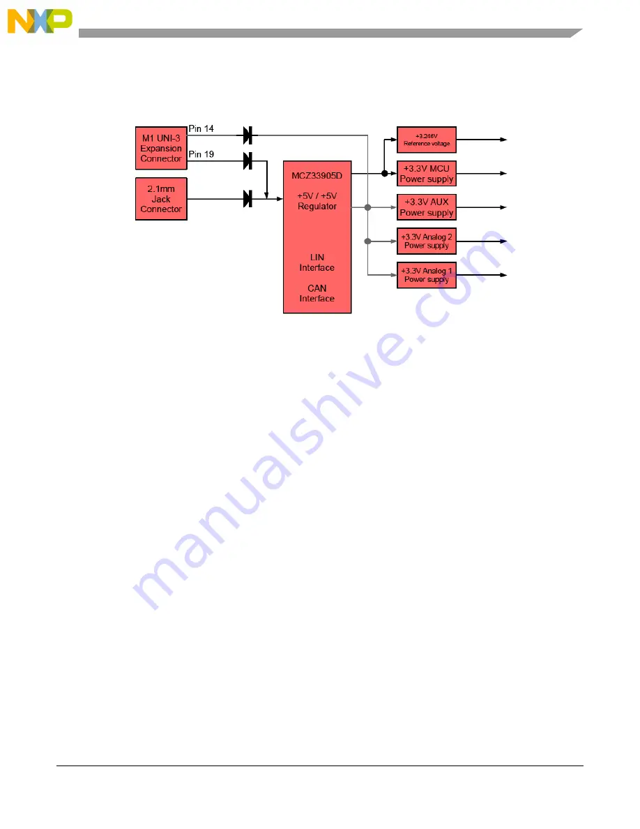
application type. The controller board provides a +5 V DC-voltage regulation for the resolver, encoder,
and FlexRAY driver, a +3.3 V DC-voltage regulation for MCU and supporting logic, and it provides
reference voltage for ADC module. The block diagram is shown in
Figure 12
.
Figure 12. Power Supply
4.8
UNI-3 PFC-PWM Signal (Power Factor Correction)
The PFC-PWM signal is used to additionally control the power stage circuit like PFC or power DC-DC
converter. These signals are connected to the MPC5604P controller pins GPIO G[6], and G[7].
4.9
UNI-3 Brake Signal
The brake signal is used to control the DC-bus resistor switch on connected power stage. It is accessible
via GPIO C[3].
4.10
CAN Bus
The FlexCAN module is a communication controller implementing the CAN protocol according to the
CAN 2.0B protocol specification, which supports both standard and extended message frames. A number
of Message Buffers (32) is also supported. Please refer to MPC5604P reference manual for detailed
description. Freescale system basis chip MC33905S with one CAN and one LIN interface is used as the
hardware interface for FlexCAN module. Jumpers JP1 and JP2 define middle or end node. The Safety
CAN module (Safety Port) doesn’t have a physical interface populated on the board but the signals are
accessible via header J13.
4.11
FlexRAY Interface
The FlexRAY module implements the FlexRay Communications System Protocol Specification, Version
2.1 Rev A. The hardware interface consists of two TJA1080 ICs, as shown in
Figure 22
.