


Debugging your Application
Getting Started with the MCUSLK for MC9S12C32 Application Module, Rev. 0
Freescale Semiconductor
15
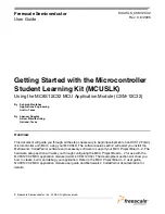
Figure 13
.
main.c in Editor Window
c.
Make changes to the contents of main.c file, if desired
d.
If you make changes to main.c, from IDE main menu bar, select File> Save
5.
Add files (if appropriate)
a.
Highlight the “sources” folder
b.
From the IDE main menu bar, select “project”; a menu will appear
c.
Select “add files”; a dialog box will appear
d.
Navigate to that directory that contains the file you want to add
e.
Highlight the filename of the file you want to add to your project
f.
Click “open”; the “add files” dialog box will appear
g.
Check the checkbox for each build target to which the file applies
h.
Click “OK”; the “add files” dialog box closes. In the “project” window, the filename of added file
will appear under the “sources” folder
6.
Build project
a.
From IDE main menu bar, select “project”
b.
Select “make”; IDE builds (assembles, compiles, and links) project; error and warnings window
will open and show error messages and warning messages, if appropriate
Debugging your Application
The following steps explain how to establish communication and upload your application software to the
MC9S12C32 MCU application module (CSM-12C32). This will allow you to debug your application
through Metrowerks’ True-Time Simulator & Real-Time Debugger using the BDM pod interface on the
MCU Project Board – 2. The
Software Setup
and
Hardware Setup
sections must be completed before
executing the steps in this section.
1.
Make sure power is applied to the project board. If not, go back and follow hardware setup section
instructions.
2.
Start debugger


