


Getting Started with the MCUSLK for MC9S12C32 Application Module, Rev. 0
6
Freescale Semiconductor
Hardware Setup
3.
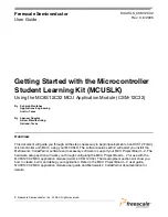
Configure the MC9S12C32 MCU application module (CSM12C32) PWR_SEL option header.
Install jumpers as shown.
PWR_SEL
4.
Configure the MC9S12C32 MCU application module (CSM12C32) USER option header. Install
jumpers as shown below.
USER
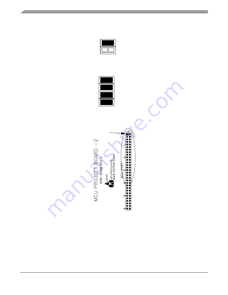
5.
Install the MC9S12C32 MCU application module in the MCU PORT connector (J5) on the project
board. Align pin 1 on the application module with pin 1 of the MCU PORT connector on the project
board as marked by Figure 2.
Figure 2. Installation of MC9S12C32 MCU Application Module
6.
Power up your host PC and connect the supplied USB cable to an available USB port on your host
PC.
NOTE
Prior to executing the following steps, all CodeWarrior development tools
for the HC(S)12 and USB 2.0 service patch software included in the
CodeWarrior Development Studio for HC(S)08 Special Edition and
HC(S)12 Special Edition 3-cd case must be installed per the instructions in
the software setup section.
1
2
1
2
3
4
4
PIN 1


