background image

Getting Started with the MCUSLK for MC9S12C32 Application Module, Rev. 0

10

Freescale Semiconductor

Development

Development

Creating and Building a Project in CodeWarrior Environment

After properly installing and registering the CodeWarrior development tools as described in the 

Software 

Setup

 section, and completing the MCU Project Board – 2 configuration as described in the 

Hardware 

Setup

 section, you can now begin to develop your application for a target microcontroller. This section will 

create and build a project under the CodeWarrior for HC(S)12 development tool platform. 

NOTE

The instructions below are slightly different from the steps described in the 
quick start pamphlet included in the CodeWarrior for HC(S)12 development 
tools CD case. The instructions below are adjusted for the MCUSLK and 
MC9S12C32 development module.

1.

Launch the CodeWarrior IDE

a.

Select: Start > Programs > Metrowerks CodeWarrior > CW12 V3.1; a menu                                                                                                                   
will appear

b.

Select: CodeWarrior IDE; IDE will start and a CodeWarrior window will appear

2.

Create a new project

a.

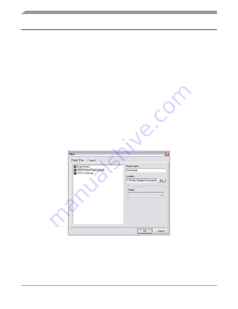
From IDE main menu bar, select: File> New; a new window will appear (see 

Figure 7

)

Figure 7. New Window

b.

Select: “HC(S)12 New Project Wizard”

c.

In the “Project name” text box, type the name you want to give the project (IDE automatically 
adds .mcp extension when it creates project)

d.

In the “Location” text box, set location where you want the project to be created

e.

Click “OK” — the first page of the new project wizard will appear (see 

Figure 8a

)

Summary of Contents for MCUSLK

Page 1: ...essary to begin development on an HCS12 Family microcontroller unit MCU using your MCUSLK The software setup section will assist you install the Metrowerks CodeWarrior software and necessary software...

Page 2: ...ce patch labeled CW12_V3_1_ICD12_USB2_0_Sim_patch exe located in the Service Pack CD found inside the supplied 3 cd case labeled CodeWarrior Development Studio for HC S 08 Special Edition and HC S 12...

Page 3: ...oject Board 2 1 To begin place the MCU Project Board 2 on a flat sturdy surface Ensure sufficient space is available around the project board to safely construct and test prototyped circuits 2 Verify...

Page 4: ...L_A in USB position VDD_SEL 5V 3 3V JP3 Sets VDD to 5 V for project board PS1_EN JP11 Enables PS1 output 15 V supply from dc dc converter to the project board J301 HIGH FULL USB ML MCUSLK Selects USB...

Page 5: ...cation signals individually for project board COM port AMPL JP7 Oscillator output at reduced amplitude 3 3 Vpp LED_EN JP6 Enables all LED outputs on project board UFEA JP10 Enables access to direct co...

Page 6: ...project board Align pin 1 on the application module with pin 1 of the MCU PORT connector on the project board as marked by Figure 2 Figure 2 Installation of MC9S12C32 MCU Application Module 6 Power up...

Page 7: ...n module board Figure 3 Installation of USB Cable NOTE Steps 8 through 11 are a one time required procedure per host PC that you intend to use with the MCU Project Board 2 and can be skipped on subseq...

Page 8: ...software automatically recommended from the Found New Hardware Wizard Screen 1 and click Next button to continue with installation 10 Installation will begin with the Found New Hardware Wizard Screen...

Page 9: ...Wizard Screen 3 12 Verify that the 3 3 V LED 5 V LED and both green and yellow USB LEDs on the MCU Project Board 2 are lit 13 Verify that the VDD LED on the MC9S12C32 MCU application module board CSM1...

Page 10: ...m the steps described in the quick start pamphlet included in the CodeWarrior for HC S 12 development tools CD case The instructions below are adjusted for the MCUSLK and MC9S12C32 development module...

Page 11: ...rked if using assembly or C mark the respective selection i Click Next Page 3 of the new project wizard will appear see Figure 9a Figure 9 New Project Wizard Page 3 and Page 4 j Select No you do not w...

Page 12: ...evelopment Figure 10 New Project Wizard Page 5 and Page 6 n Select None you do not want to specify a floating point format o Click Next Page 6 of the new project wizard will appear see Figure 10b p Se...

Page 13: ...Page 7 r Page 7 allows you to specify connections that the project should be configured to support Select P E Hardware Debugging and Motorola Serial Monitor Hardware Debugging s Click Finish the wiza...

Page 14: ...build target Your project can contain multiple build targets For this example we use the P E ICD target which uses the USB BDM pod on the MCU Project Board 2 This BDM pod provides bidirectional commu...

Page 15: ...Click OK the add files dialog box closes In the project window the filename of added file will appear under the sources folder 6 Build project a From IDE main menu bar select project b Select make ID...

Page 16: ...elect the appropriate host PC USB port being used by the BDM pod and click OK Figure 14 Debugger Window1 1 For a description of debugger windows see Table 2 Table 2 Debugger Windows Window Name Descri...

Page 17: ...sent Command pane displays program status NOTE Alternatively you can click on start continue icon in the debugger taskbar 7 Click start continue icon to resume program code execution if breakpoint occ...

Page 18: ...damages Typical parameters which may be provided in Freescale Semiconductor data sheets and or specifications can and do vary in different applications and actual performance may vary over time All op...

Reviews: