8
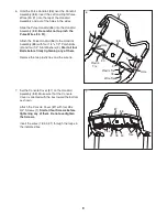
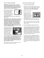
3. With the help of a second person, carefully tip
the incline trainer down so that the Base (80) is
flat on the floor.
Attach a Wheel (12) to each side of the Base
(80) with a 3/8" x 2 1/2" Bolt (6) and a 3/8" Nut
(7) (only one side is shown).
6
7
12
80
4
89
34
87
A
A
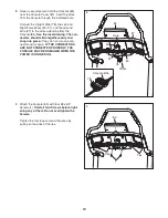
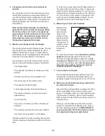
4. Set the Console Cover (87) face down on a soft
surface. Remove the plastic ties from the bottom
of the Handrail Assembly (88). Press the U-nuts
(34) back into place, if necessary.
Remove the two Screws (A) from the Console
Back (89). Note: The Screws may not be in the
indicated holes. Separate the Console Back
from the Console Cover (87). Discard the
Screws.
Press the Left and Right Accessory Trays (99,
100) out of the Console Cover (87).
99
100
34
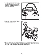
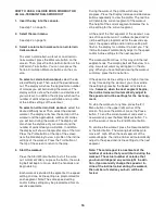
5. Have a second person hold the Handrail
Assembly (88) near the Handrail Brackets (76).
Insert the Upright Wire (78) through the
indicated hole in the bottom of the Handrail
Assembly and out of the hole near the top of the
Handrail Assembly.
Set the Handrail Assembly (88) on the Handrail
Brackets (76).
Make sure not to pinch the
Upright Wire (78)
.
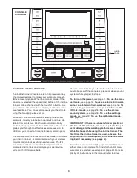
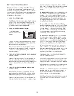
Attach the Handrail Assembly (88) to the
Handrail Brackets (76) with four 3/8" x 1 1/2"
Patch Bolts (4) and four 3/8" Star Washers (8);
start all four Patch Bolts before tightening
any of them.
5
8
8
4
4
Hole
76
76
8
4
8
4
78
88
Hole
88
3

