7
1.
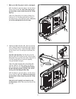
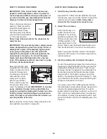
Make sure that the power cord is unplugged.
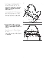
With the help of a second person, tip the incline
trainer onto its left side.
Have the second per-
son hold the incline trainer to prevent it from
tipping.
Attach four Base Feet (10) and two Base Foot
Spacers (11) to the Base (80) with four #8 x 1"
Tek Screws (2) in the locations shown.
Be care-
ful not to overtighten the Tek Screws.
1
2
2
10
10
10
11
80
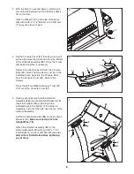
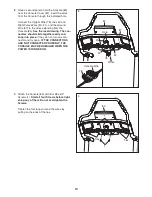
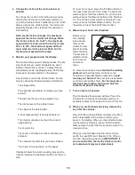
2. Identify the Right Upright (79), which is marked
with a “Right” sticker and hold the Right Upright
near the incline trainer. Orient the Right Upright
so that the curve in the Upright is positioned as
shown.
See the inset drawing.
Tie the wire tie in the
Right Upright (79) around the end of the Upright
Wire (78). Then, pull the other end of the wire tie
until the Upright Wire is routed completely
through the Right Upright.
Attach the Right Upright (79) to the Base (80)
with two 3/8" x 3 1/2" Patch Bolts (5) and two
3/8" Star Washers (8).
Start both Patch Bolts
before tightening either of them. Be careful
not to pinch the Upright Wire (78).
With the help of a second person, tip the incline
trainer onto its right side.
Have the second per-
son hold the incline trainer to prevent it from
tipping.
Attach the Left Upright (not shown) as de-
scribed above.
Note: There are no wires on the
left side.
2
78
79
80
8
79
78
Wire
Tie
5
11
10
2
2
Wire
Tie
Curve

