

– 7 –
CE-50 / CE-75 / TE-50 / TE-75 / TE-75S / TE-125 / TE-125BF
EN
DRAFT
ONL
Y
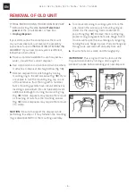
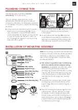
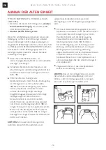
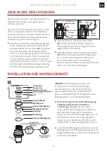
PLUMBING CONNECTION
I
f dishwasher and/or overflow is
not to be
connected
go on to next section.
If you are utilizing a dishwasher, this should
preferably be connected directly to the relevant
connection in the siphon. If a dishwasher connection
is not available in the siphon, complete the following
procedure:
X
X
Using a blunt instrument (steel punch or wooden
dowel), knock out entire plug (fig.
2A
). Do not
use a screwdriver or sharp instrument. (When
knockout plug falls into disposer, you may remove
it or grind it up when the disposer is used. This
will not damage the disposer in any way, but may
take some time to grind).
2B
Overflow
Hose
Dishwasher
Hose
2A
Overflow
Connection
Dishwasher
Connection
Siphon
Connection
X
X
Connect overflow hose (fig.
2B
) using hose clamp.
If hose size is different, you need a stepped
rubber adaptor.
X
X
Connect dishwasher hose (fig.
2B
) using hose
clamp. Make sure all plumbing connections are
tight and in accordance with all plumbing codes
and ordinances. Run water and check for leaks.
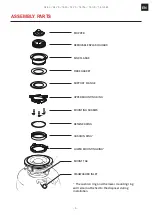
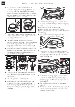
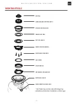
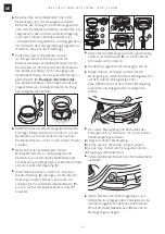
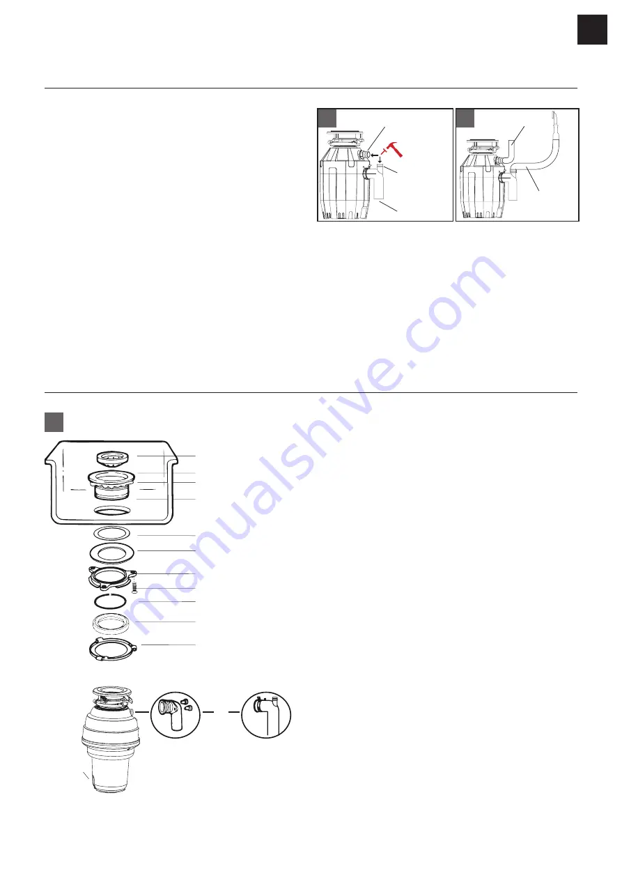
INSTALLATION OF MOUNTING ASSEMBLY
Removable
Splash Guard
Sink Flange
Plumber’s Putty
(not included)
Sink
Upper Mounting Ring
Mounting Screw
Retainer Ring
Cushion Ring
Lower Mounting Ring
Rubber Gasket
Reset
Button
Fiber Gasket
Support Flange
Elbow Flange & Screw Set (2)
Elbow
Spring Clamp Ring
Elbow
Groove
OR
CE-XX
TE-XX
3
NOTE:
The mounting components are assembled out
of the box in the same order they will be assembled
on the sink, so please pay close attention to the
order of the mounting system components before
you disassemble them.
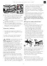
X
X
The cushion ring and the lower mounting ring
will remain attached to the disposer during
installation
. Disassemble the other components
of the mounting assembly by rotating lower
mounting ring clockwise until the lower mounting
ring tabs slide off from the upper mounting ring
ramp. This will allow you to separate the upper
assembly from the remaining lower mounting
assembly.
X
X
Unscrew the 3 mounting screws until the upper
mounting ring can be moved to the top of the
support flange. Remove the retainer ring with a
screw driver.
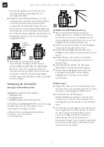
X
X
Keep the remaining parts placed together in the
order they were removed. Before you connect
the disposer to the mounting assembly under
the sink, make sure the lower mounting ring is in
place and the black cushion ring is still engaged
properly to the top of the disposer opening. (Do
not remove the cushion ring.)
Summary of Contents for CE-50
Page 2: ...2 CE 50 CE 75 TE 50 TE 75 TE 75S TE 125 TE 125BF EN...
Page 63: ...63 CE 50 CE 75 TE 50 TE 75 TE 75S TE 125 TE 125BF ES...
Page 65: ...65 CE 50 CE 75 TE 50 TE 75 TE 75S TE 125 TE 125BF EL FRANKE X X X X Z Z X X 9 9 Z Z...
Page 67: ...67 CE 50 CE 75 TE 50 TE 75 TE 75S TE 125 TE 125BF EL...
Page 74: ...74 CE 50 CE 75 TE 50 TE 75 TE 75S TE 125 TE 125BF EL X X X X OFF X X 3 X X X X 7...
Page 75: ...75 CE 50 CE 75 TE 50 TE 75 TE 75S TE 125 TE 125BF EL 7...
Page 76: ...76 CE 50 CE 75 TE 50 TE 75 TE 75S TE 125 TE 125BF EL Z Z 15 25 2002 96...
Page 77: ...77 CE 50 CE 75 TE 50 TE 75 TE 75S TE 125 TE 125BF EL...
Page 103: ...103 CE 50 CE 75 TE 50 TE 75 TE 75S TE 125 TE 125BF RU FRANKE X X X X Z Z X X 9 9 Z Z...
Page 105: ...105 CE 50 CE 75 TE 50 TE 75 TE 75S TE 125 TE 125BF RU...
Page 112: ...112 CE 50 CE 75 TE 50 TE 75 TE 75S TE 125 TE 125BF RU X X X X X X 3 X X...
Page 113: ...113 CE 50 CE 75 TE 50 TE 75 TE 75S TE 125 TE 125BF RU X X 7 7...
Page 114: ...114 CE 50 CE 75 TE 50 TE 75 TE 75S TE 125 TE 125BF RU Z Z 15 25 2002 96 EC...
Page 115: ...115 CE 50 CE 75 TE 50 TE 75 TE 75S TE 125 TE 125BF RU...
Page 127: ...127 CE 50 CE 75 TE 50 TE 75 TE 75S TE 125 TE 125BF TR...