– 9 –
CE-50 / CE-75 / TE-50 / TE-75 / TE-75S / TE-125 / TE-125BF
EN
DRAFT
ONL
Y
Electrical connection
X
Z
Connect disposer to appropriate
household current only.
The receptacle to which this appliance is connected
must be controlled by a switch.
WARNING:
Improper connection of the
equipment-earthing conductor can result in a
risk of
electric shock
. Check with a qualified
electrician or serviceman if you are in doubt as to
whether the appliance is
properly earthed
. Do not
modify the plug provided with the appliance if it will
not fit the outlet. Have a
proper outlet installed
by
a qualified electrician.
Earthing instructions
FOR WASTE DISPOSERS EQUIPPED WITH AN
EARTHED PLUG-IN POWER CORD
X
Z
This appliance must be earthed. In the event of
a malfunction or breakdown, earthing provides
a path of least resistance for electric current to
reduce the risk of electric shock. This appliance
is equipped with a cord having an equipment-
grounding conductor and a grounding plug.
X
Z
The plug must be plugged into an appropriate
outlet that is properly installed and grounded in
accordance with all local codes and ordinances.
X
Z
If the supply cord is damaged it must be replaced
by the manufacturer, its service agent or similarly
qualified person in order to avoid a hazard.
Removing an attached power cord or plug voids
the warranty.
The following UK Electrical Section is for United
Kingdom only - skip if not applicable
.
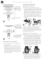
WHEN USING THE ATTACHED PRE-WIRED MOULDED
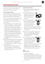
PLUG AND LEAD (fig.
3A
)
9
These disposers are engineered to be connected
to a 220/240 V~-50/60 Hz electrical supply
through the attached three-pin plug and into a
wired socket.
9
The disposer must be protected by a BS 1363 13
Amp fuse. The fuse is included within the molded
plug and lead, attached to the disposer.
9
The 13 Amp double pole switched spur switch
should be positioned higher than the sink
countertop and at a minimum of one meter from
the side of the sink, away from water splashes
and out of the reach of children. This spur switch
must be a double pole with at least 3 mm contact
separation in each pole. 20 Amp DP switches BS
3676 meet this condition.
9
To avoid accidentally leaving the disposer running,
a switch with a neon indicator lamp is suggested.
9
A 13 Amp ASTA approved fuse, to BS 1363 must
be fitted in the fuse carrier of this spur switch.
ELECTRICAL CONNECTIONS:
X
X
Simply insert the plug into the socket wired as
previously described.
WHEN NOT USING THE PRE-WIRED PLUG BUT
WIRING DIRECT WITH FIXED WIRING (fig.
3B
).
9
The switches used must be double pole type and
have at least a 3 mm contact separation in each
pole (20 Amp DP switches to BS 3676 meet this
requirement).Prepare the tips of the wires of the
electrical lead and attach to the junction box.
9
Disconnect the junction box from the electrical
supply before making the following connections:
9
The green and yellow wire must be connected to
the terminal marked in one of the following ways:
– with the letter “
E
”
– by the earth symbol (
)
– coloured green or green and yellow.
9
The brown wire must be connected to the
terminal that is marked with the letter „
L
“.
9
The blue wire must be attached to the terminal
that is marked with the letter „
N
“.
(
NOTE
: As your disposer has a molded plug on the
lead and the plug is not to be used, cut it off and
dispose of it wisely. A moulded plug with a loose
lead with disconnected wires can be hazardous as
an
electrical shock hazard
could occur should such
a plug be inserted into a 13 Amp socket anywhere
within the home.)
IS THE DISPOSER EARTHED?
WARNING:
this appliance
must be earthed
!
In the event of a malfunction of breakdown,
earthing reduces the
risk of shock
. This disposer
must be connected to an earthed, metal, permanent
wiring conductor and connected to the equipment
earthing terminal or lead on the disposer.
Summary of Contents for CE-50
Page 2: ...2 CE 50 CE 75 TE 50 TE 75 TE 75S TE 125 TE 125BF EN...
Page 63: ...63 CE 50 CE 75 TE 50 TE 75 TE 75S TE 125 TE 125BF ES...
Page 65: ...65 CE 50 CE 75 TE 50 TE 75 TE 75S TE 125 TE 125BF EL FRANKE X X X X Z Z X X 9 9 Z Z...
Page 67: ...67 CE 50 CE 75 TE 50 TE 75 TE 75S TE 125 TE 125BF EL...
Page 74: ...74 CE 50 CE 75 TE 50 TE 75 TE 75S TE 125 TE 125BF EL X X X X OFF X X 3 X X X X 7...
Page 75: ...75 CE 50 CE 75 TE 50 TE 75 TE 75S TE 125 TE 125BF EL 7...
Page 76: ...76 CE 50 CE 75 TE 50 TE 75 TE 75S TE 125 TE 125BF EL Z Z 15 25 2002 96...
Page 77: ...77 CE 50 CE 75 TE 50 TE 75 TE 75S TE 125 TE 125BF EL...
Page 103: ...103 CE 50 CE 75 TE 50 TE 75 TE 75S TE 125 TE 125BF RU FRANKE X X X X Z Z X X 9 9 Z Z...
Page 105: ...105 CE 50 CE 75 TE 50 TE 75 TE 75S TE 125 TE 125BF RU...
Page 112: ...112 CE 50 CE 75 TE 50 TE 75 TE 75S TE 125 TE 125BF RU X X X X X X 3 X X...
Page 113: ...113 CE 50 CE 75 TE 50 TE 75 TE 75S TE 125 TE 125BF RU X X 7 7...
Page 114: ...114 CE 50 CE 75 TE 50 TE 75 TE 75S TE 125 TE 125BF RU Z Z 15 25 2002 96 EC...
Page 115: ...115 CE 50 CE 75 TE 50 TE 75 TE 75S TE 125 TE 125BF RU...
Page 127: ...127 CE 50 CE 75 TE 50 TE 75 TE 75S TE 125 TE 125BF TR...


