background image

ServerIron 4G Series

October 2008

© 2008 Foundry Networks, Inc.

4 - 5

you can remove one of the supplies without interrupting operation.  The remaining supply provides enough power 
for all the ports. 

The RPS5 power supply is 100VAC @ 3.5A, 240VAC @ 1.5A, 50-60Hz, auto-sensing, and auto-switching. The 
RPS5DC is a 36-72 VDC power supply.

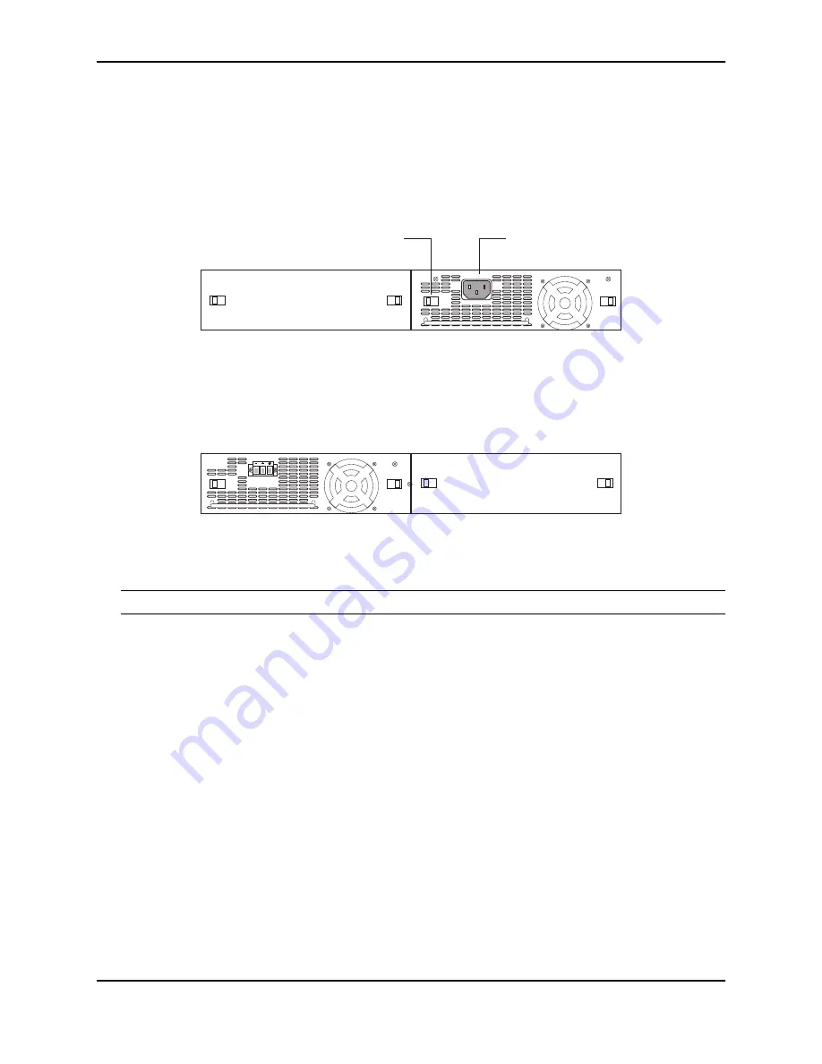
Figure 4.5 on page 4-5 shows a rear view of a ServerIron 4G containing one RPS5 power supply.    

Figure 4.5   RPS5 Power Supply

Figure 4.6 on page 4-5 shows a rear view of a ServerIron 4G containing one RPS5DC power supply. 

Figure 4.6   RPS5DC power supply

Installing ServerIron 4G Series

WARNING: The procedures in this manual are for qualified service personnel. 

This section contains describes how to install the ServerIron 4G series devices.

Site Preparation

This section describes the procedures required to prepare the site for installatoin.

Cabling Infrastructure

Ensure that the proper cabling is installed in the site.  See “Technical Specifications” on page 4-21 or 
www.foundrynetworks.com for a summary of supported cabling types and their specifications.

Installation Location

Before installing the device, prepare its location and orientation relative to other devices and equipment.  Allow at 
least 3" of space at the front of the device for the twisted-pair, fiber-optic, and power cabling.  Also, allow a  
minimum of 3" of space between the sides and the back of the device and walls or other obstructions.

Package Contents

The ServerIron 4G Series systems ship with the following items.  Review the list below and verify the contents.  If 
any items are missing, contact the place of purchase.

Foundry Networks ServerIron 4G or ServerIron 4G-SSL device

115V AC power cable (for AC sourced devices)

Plastic Latch

AC Power
Connector

Power Supply (standard)

Summary of Contents for ServerIron 4G

Page 1: ...e eCommerce and service provider sites ServerIron 4G Series highlights include ASIC Based Application Processors Choice of non SSL and SSL Integrated switches Hardware SSL Acceleration ServerIron 4G S...

Page 2: ...ponents This section describes hardware components that are common to the ServerIron 4G Series SSL and non SSL Stackable device switches Front Panel Figure 4 4 on page 4 3 shows the ServerIron 4G Seri...

Page 3: ...tes power supply is not powered on or not present PS2 Green ON Indicates power supply is powered on OFF Indicates power supply is not powered on or not present BP Out Green ON Indicates BP is transmit...

Page 4: ...of the other fan The following fan speeds are available low medium high You can change the settings of the temperature thresholds using the following command FastIron fan speed lo Syntax fan speed lo...

Page 5: ...section describes the procedures required to prepare the site for installatoin Cabling Infrastructure Ensure that the proper cabling is installed in the site See Technical Specifications on page 4 21...

Page 6: ...supply it might be easier to install it before mounting the device See Installing a Redundant Power Supply on page 4 8 3 Install the device on a desktop on the wall or in an equipment rack See Install...

Page 7: ...DC input circuit to a ServerIron 4G Series DC power supply part number RPS5DC and RPS X424 DC make sure there is a 10 amp listed circuit breaker minimum 48VDC double pole on the input to the terminal...

Page 8: ...r supply locking screw located in the center rear of the device illustrated below 2 If the empty power supply bay has a cover plate press inward on the two latches near the edges of the cover plate to...

Page 9: ...tely in the slot so that the connectors on the back of the supply are fully engaged with the pins on the power backplane CAUTION Make sure you insert the power supply right side up It is possible to i...

Page 10: ...as illustrated in Figure 4 7 on page 4 10 4 Proceed to Powering On the System on page 4 10 Figure 4 7 Installing the Device in a Rack Powering On the System After you complete the physical installati...

Page 11: ...is your assurance that the power cord can be used safely with the device 4 Verify that the LED for each power supply is a solid green 5 Verify proper operation by observing the LEDs All the port LEDs...

Page 12: ...sion parameters as follows Baud 9600 bps Data bits 8 Parity None Stop bits 1 Flow control None When you establish the serial connection to the system press Enter to display the CLI prompt in the termi...

Page 13: ...a Terminal or PC Assigning Permanent Passwords By default the CLI is not protected by passwords To secure CLI access Foundry strongly recommends assigning passwords NOTE You cannot assign a password...

Page 14: ...t enter the following command to change to the Privileged level of the EXEC mode FastIron enable 2 Access the CONFIG level of the CLI by entering the following command FastIron configure terminal Fast...

Page 15: ...fault the CLI displays network masks in classical IP address format example 255 255 255 0 You can change the display to the prefix format NOTE If your network uses a BootStrap Protocol BootP server or...

Page 16: ...r switches and routers via fiber ports See Connecting to a Fiber Port on page 4 16 Automatic MDI MDIX Detection All 100 1000 Ethernet Copper ports on the Foundry FastIron devices support automatic Med...

Page 17: ...the Fiber Optic Connectors on page 4 17 3 Gently insert the cable connector s a tab on each connector should face upward into the port connector s until the tabs lock into place 4 Observe the link and...

Page 18: ...perating correctly Verify that the transmit port on the Foundry device is connected to the receive port on the other network device and that the receive port on the Foundry device is connected to the...

Page 19: ...is connected to the transmit port on the connected device Verify that the port has not been disabled through a configuration change You can use the CLI If you have configured an IP address on the dev...

Page 20: ...at any CLI level Changing the Temperature Warning Level The Foundry device sends a warning message whenever the device s internal temperature reaches the default or configured warning temperature The...

Page 21: ...e To do so enter the following command at any level of the CLI Syntax show cpu The CPU Usage field shows the percentage of management module CPU used by each task The total CPU usage may not add up to...

Page 22: ...agnetic Emission ICES 003 Electromagnetic Emission FCC Class A EN 55022 CISPR 22 Class A VCCI Class A EN 61000 3 2 Power Line Harmonics EN 61000 3 3 Voltage Fluctuation Flicker EN 61000 6 3 Electromag...

Page 23: ...d Weight of Chassis Height Width Depth Weight 2 60 in 6 6 cm 17 63 in 44 8 cm 19 6 in 47 2 cm 25 35 lbs 11 5 kg fully loaded including dual redundant power supplies 17 5 lbs 7 94 kg empty 4 lbs 18 kg...

Page 24: ...be required to correct the interference at their own expense CAUTION Changes or modifications made to this device which are not expressly approved by Foundry Net works could void the user s authority...

Page 25: ...PS5DC CISPR 22 Class A FCC Class A VCCI Class A IC ICES 003 Class A Canada EN55022 Class A Harmonic Current Emissions Class A EN61000 3 2 with Amendment 14 1999 Voltage Fluctuations and Flicker EN6100...

Page 26: ...0 95 non condensing Operating altitude up to 10 000 feet above sea level Operating noise 47 dB A Storage temperature 40 to 185 F 40 to 85 C Storage altitude up to 15 000 feet above sea level Cooling...

Reviews: