background image

VR800 Owner’s Manual (MIDI Synchronization)

68

MIDI sync function

The following are examples concerning general types of systems using MIDI related functions contained in the VR800.

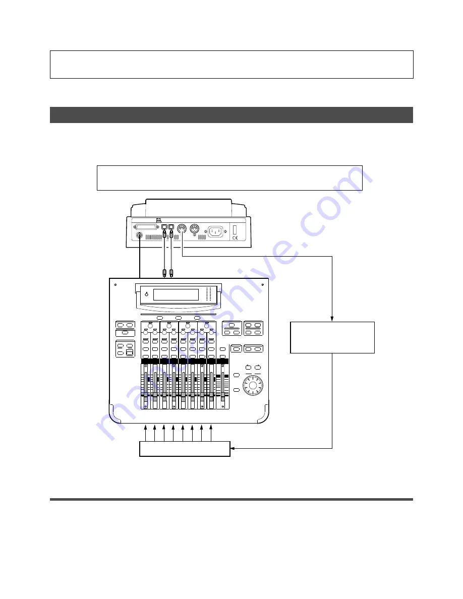
MIDI clock sync system

By setting any desired meter at any desired point of the programmable tempo map contained in the VR800, and by
output of a MIDI clock and song position pointer according to the setting, a hardware type MIDI sequencer can be
synchronized as a MIDI clock slave.  Consequently, in this system, the VR800 will be the master and the MIDI sequencer
the slave.

* Restore the default settings on VR800.

* Check for the correct program and proper sampling frequency.

Connecting external equipment (Refer to connecting schematic)

1. Connect the VR800 MIDI OUT to MIDI IN of the MIDI sequencer.

2. Set the MIDI sequencer for "external sync mode (EXTERNAL SYNC) by MIDI clock."

* Refer to the Owners Manual of the equipment in use for details.

SCENE MEMORY

REC BUSS

EFF EDIT

SELECTED EQ

EQ/HI

EQ/HI-MID

EQ/LO-MID

EQ/LO

SETUP

CURRENT SCENE STATUS

KEY MODE

+10

0

-10

-20

-30

-40

-

+10

0

-10

-20

-30

-40

-

+10

0

-10

-20

-30

-40

-

+10

0

-10

-20

-30

-40

-

+10

0

-10

-20

-30

-40

-

+10

0

-10

-20

-30

-40

-

+10

0

-10

-20

-30

-40

-

GAIN

FREQ

PAN

Q

PAN

ON

ON

ON

ON

ON

ON

ON

SOLO

SOLO

SOLO

SOLO

SOLO

SOLO

SOLO

EQ EDIT

EQ EDIT

EQ EDIT

EQ EDIT

EQ EDIT

EQ EDIT

EQ EDIT

EQ EDIT

SOLO

ON

ON

SOLO

EQ LIBRARY

STORE

RECALL

EQ ON

EFF LIBRARY

STORE

RECALL

EFF2

EFF1

STORE

RECALL

SOLO

   +1/

   /-1

DATA

EXIT

ENTER

FREQ

Q

FREQ

Q

FREQ

Q

GAIN

GAIN

GAIN

1-8 ANALOG IN

9-16 ADAT IN

17-20 EFF RTN

PAGE SELECT

SYSTEM

MIDI

PHASE

GROUP

ROUTING/

PAIR/

CH VIEW

METER

CHANNEL/

+10

0

-10

-20

-30

-40

-

0

-10

-20

-30

-60

-

-40

MMC SEND

PAN

PAN

PAN

PAN

PAN

PAN

-40

-36

-24

-18

-12

-9

-6

-3

OL

ST BUSS/SOLO

L

R

METER

POWER

AC IN

OUT

IN

MIDI

IN

OUT

DATA

SCSI

WORD OUT

OPTICAL

MIDI Sequencer

MIDI clock & song position pointer

MIDI IN

MIDI OUT

MIDI IN

MIDI sound sources

Summary of Contents for VR800

Page 1: ...PBOARD AUTO RTN OUT IN END OUT IN START EJECT ACCESS 5 6 7 8 OL 24 12 6 0 1 2 3 4 RECORD TRACK 4 3 2 1 5 6 7 8 EXECUTE YES EXIT NO DISP SEL UNDO REDO EDIT HOLD STORE SETUP JOG VARI PITCH SCRUB LOCATE AUTO PLAY PGM SEL AUTO RTN TIME BASE SEL SHUTTLE LOCATE REC END LOCATE ABS 0 CLIPBOARD PLAY PUNCH AUTO OPTICAL A SYNC PREVIEW ...

Page 2: ...od of time 15 Object and Liquid Entry Care should be taken so that objects do not fall and liquids are not spilled into the enclosure through openings 16 Damage Requiring Service The appliance should be serviced by qualified service personnel when A The power supply cord or the plug has been damaged or B Objects have fallen or liquid has been spilled into the appliance or C The appliance has been ...

Page 3: ...recording 39 Manual Punch In Out recording 40 preparation 40 Rehearsing manual punch in out recording 40 Manual punch in out Take 41 Undo redo manual punch in out recording 42 RecordingtoaMetronomeSound 43 DigitalRecording 45 Digital recording from an external digital device 45 Digital recording to an external device 46 StoringaLocatePoint EditPoint 48 Storing and editing the locate points to the ...

Page 4: ...tion 84 Loadingdata 85 Saving and loading song data via a SCSI drive 86 Quick Troubleshooting 87 ChangingtheInitialSettings SETUPmode 88 Selecting SETUP mode 89 Settingatimesignature 90 Setting a tempo 92 Settingthemetronomefunction 93 Setting a preroll value 94 SettingMIDIsyncoutputsignal 95 Setting an MTC frame rate 96 Setting an MTC offset value 96 Setting MTC Offset mode 97 Setting the slave m...

Page 5: ... Out Auto Locate are available You can also locate ABS 0 or REC END regardless of the edit point locate point You can set a preroll time of 0 to 10 seconds A Disk Remain Display function offers a clear indication of available recording time and disk space in mono track recording You can choose the Time Base from ABS MTC and BAR BEAT CLK Introduction Thank you for purchasing the Fostex Model VR800 ...

Page 6: ...data the HD ACCESS LED is lit or flashing Otherwise not only will you lose recorded data but you may damage to the unit FOSTEX is not responsible for the data lost during operation of the unit Before you change the location of the VR800 pack the unit in the shipping carton or an impact resistant case Make sure that the unit is kept free from external vibration or impact since the unit is very sens...

Page 7: ...H CLIPBOARD AUTO RTN OUT IN END OUT IN START EJECT ACCESS 5 6 7 8 OL 24 12 6 0 1 2 3 4 RECORD TRACK 4 3 2 1 5 6 7 8 EXECUTE YES EXIT NO DISP SEL UNDO REDO EDIT HOLD STORE SETUP JOG VARI PITCH SCRUB LOCATE AUTO PLAY PGM SEL AUTO RTN TIME BASE SEL SHUTTLE LOCATE REC END LOCATE ABS 0 CLIPBOARD PLAY PUNCH AUTO OPTICAL A SYNC PREVIEW Rear panel Top panel PUN CH IN O UT Side panel ...

Page 8: ...he VR800 in playback monitoring mode You can also use these select keys to select tracks to Copy Paste Move Paste Erase and other editing features as well as to execute the digital scrubbing Note You can record on real tracks 1 8 in real time but not on additional tracks 9 24 If you are using an MO drive as the current drive you can record only two tracks simultaneously If you try to record more t...

Page 9: ...ove Paste functions Refer to page 59 for more information on previewing data at the CLIPBOARD OUT point 7 Exit No key EXIT NO EJECT This key is the counterpart of the EXECUTE YES key Press this key to cancel an operation When you use a removable SCSI disk pressing this key while holding down the SHIFT key will eject the disk 8 Execute Yes key EXECUTE YES Press this key to confirm the edit operatio...

Page 10: ...00 will enter the digital scrub mode At this point press the desired RECORD TRACK select key to digitally scrub the selected track playback using the JOG dial Refertopage58formoreinformationonDigitalScrubmode Refer to page 54 for more information on the Locate function Refer to page 51 for more information on editing data using the LOCATE key 16 Locate key LOCATE LOC MEM Use this key to start the ...

Page 11: ...UP JOG VARI PITCH SCRUB LOCATE AUTO PLAY PGM SEL AUTO RTN TIME BASE SEL SHUTTLE LOCATE REC END LOCATE ABS 0 CLIPBOARD PLAY PUNCH AUTO PREVIEW 20 Fast forward button F FWD Pressing this button while the VR800 is stopped will start fast forwarding at low speed at first then gradually accelerate to 30 times speed If you press this button while the VR800 is playing cueing fast forwarding with sound st...

Page 12: ...ween AUTO PUNCH on and off Refer to page 54 for more information on these operations Refer to page 40 for more information on the Punch In Out operation using a foot switch STOP PLAY REW F FWD Press the STORE key and press the CLIPBOARD IN key The CLIPBOARD IN point will be stored This data can be used as locate data Press the STORE key and press the CLIPBOARD OUT key The CLIPBOARD OUT point will ...

Page 13: ...FT key when the recorder is stopped you can preview the fade in part at the stored AUTO RTN START point Refertopage48formoreinformationonsettingandediting the AUTO RTN START point Refer to page 54 for more information on theAuto Return andAuto Repeat functions Refer to page 59 for more information on previewing data at theAUTO RTN START point Refertopage48formoreinformationonsettingandediting the ...

Page 14: ...I equipment can be connected in a chain Refer to the Quick Operation Guide for information on connecting an external SCSI drive Refer to page 75 for more details on SAVE LOAD using a SCSI device Note You can save the data recorded on the current drive formatted in Master 8ch mode and Master 4ch mode to a DAT You cannot save data recorded in ADAC 8ch mode You can save only the data recorded on the ...

Page 15: ...el 8051 Refer to page 68 for more information on using the MIDI IN jack 5 MIDI IN jack MIDI IN Connector DIN 5 pin Connect this jack to the MIDI OUT jack of an external MIDI device You can control the VR800 remotely by inputting MMC MIDI Machine Control command or FEX Fostex System Exclusive Message here Side Panel PUNCH IN OUT 1 6 Word Out jack WORD OUT Connector BNC Word clock signal from the VR...

Page 16: ...evice The IDE indicator lights up if the current drive is an E IDE hard disk The name of the SCSI drive The name is different depending on the type of device Indicating a recording mode used during for matting Display when the power is turned on When you turn on the power to the VR800 and the connected external SCSI drive a formatted removable disk or hard disk the display shows the Initial messag...

Page 17: ...se is ABS Time base is BAR BEAT CLK Time base is MTC Note If only a SCSI drive is connected to the VR800 SCSI lights up If an 3 5 inch internal E IDE hard disk has been installedbutnoexternalSCSIdeviceisconnectedasthecurrent drive IDE lights up If a SCSI drive is connected turned on and specified as the current drive and an internal hard disk is also connected only SCSI will light up Displayexampl...

Page 18: ...the REMAIN value by the number of tracks you wish to record The value calculation includes all data from real tracks and additional tracks If some data exists on the additional tracks but not on the real tracks the space and time consumed by the additional tracks are considered during the calculation For more information on the REMAIN display please refer to Recording method and REMAIN display in ...

Page 19: ...e no keys and buttons do not function at all Action to take If this message appears please use the following procedures 1 Leave the disk inside the SCSI drive and turn off the power to the VR800 and all connected devices 2 Turn on the power to the SCSI drive 3 Make sure that the orange LED on the SCSI drive lights up in green and that the disk is not being accessed Then turn on the power to the VR...

Page 20: ...e time that is obtained by adding a certain value MTC offset value to the ABS value BAR BEAT CLK indicates the position in a song created in the internal Tempo Map according to MIDI clock and Song Position Pointer The following diagrams depict the relationship among these three types of the Time Base This chapter describes some basic items that you need to know before you start operating the VR800...

Page 21: ...cording is five minutes 3 minutes 2 minutes That is the area between three minutes and ten minutes that corresponds to 25 minutes of recording space in terms of ABS time is still unrecorded When you try to play or fast forward this unrecorded area the time counter on the display will count but the VR800 will not access the disk However MTC will be output when you try to play this area On the VR800...

Page 22: ...gram This example shows a temporary title automatically named to program 1 right after you format the disk Note As described in the REMAIN indicator creating additional Programs will consume a small amount of disk space program 1 program 2 program 3 program 4 program 5 program 6 program 7 program 8 program 9 You can set up to 99 programs independent containers Refer to page 33 for more information...

Page 23: ...s as is in real time If you wish to play back data on an Additional track first use the Track Exchange function to move the data to a Real track Also you need to move the data to a Real track if you wish to check the REC END point of a song on an Additional track Note Data on the Additional tracks also affects the REMAIN value If Real tracks contain no data but Additional tracks contain data the a...

Page 24: ...de press the RECORD TRACK select key to set the track READY then press only the RECORD button Pressing the RECORD button again will cause the VR800 to enter playback monitoring mode Under this condition only the READY track enters input monitoring mode on stand by for recording The following example shows track 5 in Input Monitoring mode and other tracks in Playback Monitoring mode This example sh...

Page 25: ...ours of ABS time and you can intentionally create silence between two audio files In this case a silent part is counted as a 0 file Therefore audio files and 0 files are consecutively created as shown in the diagram below The total number of these audio files and 0 files is called the number of events The maximum number of events is 512 per track tracks 1 24 After the number of events reaches 507 ...

Page 26: ...et the Clipboard In point and the Clipboard Out points within an unrecorded range to copy the area the area that contains multiple audio files and you wish to optimize between them then paste the data starting from the same Clipboard In point Multiple audio files within this range will become a single audio file Hints Make sure that you set the Clipboard In Out points within zero files and that yo...

Page 27: ...er 8ch mode If you are using a removable SCSI disk as the current drive format it in Master 4ch mode or ADAC 8ch mode Formatting a removable SCSI disk in Master 8ch mode will not provide enough recordable space Note that data recorded on a disk formatted in ADAC 8ch mode cannot be saved or loaded using a DAT or adat Only the data recorded on the Master 8ch mode disk can be saved or loaded to from ...

Page 28: ...ing mode menu with ADAC 8ch ADAC 8ch mode and SURE flashing Turn the JOG dial to select the desired recording mode Turn the JOG dial to select ADAC 8ch Master 8ch or Master 4ch according to the media or your application If you wish to format another removable disk insert the disk and repeat the procedure described above Press and hold the RECORD button and press the EXECUTE YES key The VR800 start...

Page 29: ...the disk in selected record ing mode REMAIN lights up on the display and the negative value of the unformatted disk area size will count down as the format operation progresses Please wait a while When formatting is complete COMPLETED lights up on the display and the VR800 stops spinning the disk Press the EXIT NO key or the STOP button to exit SETUP mode Formatting will automatically create one P...

Page 30: ...ess the EXIT NO key or the STOP button The display will change from the REMAIN indication for the backup disk to the Time Base indication for the cur rent drive Formatting a current drive disk 3 5 inch E IDE hard disk When you format or re format a 3 5 inch E IDE hard disk make sure that the IDE indicator is lit in the DRIVE section of the display see the Note below and follow the steps explained ...

Page 31: ... flashes A different message appears depending on the type of format used by the disk as shown below If you turn the JOG dial Eject appears and pressing the EXECUTE YES key ejects the disk Press and hold the RECORD button and press the EXECUTE YES key The VR800 starts formatting REMAIN lights up on the display and the negative value of the unformatted disk area will count down as the for mat opera...

Page 32: ...ew program If you wish to name the program continue the steps below In either case you can change the title later as explained in Editing a program title 5 Press the EXECUTE YES key The VR800 will automatically enter Title Edit menu in SETUP mode You can enter a title for program 2 t and flash alternately If you prefer the default name press the EXIT NO key 4 Turn the JOG dial clockwise The questi...

Page 33: ... programs exist on the disk you need to select a program to record play or edit This section describes how to select a program Note You cannot use the program change function if the VR800 is in SETUP mode 2 Turn the JOG dial to select the desired program number flashing Rotating the JOG dial counter clockwise decreases the number Rotating it clockwise increases the number If you turn the JOG dial ...

Page 34: ...ograms data will move in the same way Therefore it will appear that PGM 07 has been deleted If you delete the last program PGM 07 in this example PGM 07 will be completely deleted If you try to deleted PGM 05 only the data of PGM 05 will be deleted and the data of PGM 06 will move into PGM 05 1 Press the SETUP key while the VR800 is stopped The VR800 will enter the SETUP mode and display the first...

Page 35: ...rchy level of the SETUP menu that was selected before you turned off the power 2 Turn the JOG dial to select the first hierarchy level of the Title Edit menu The symbols t and will flash alternately The currently selected program number will also appears You can also use the HOLD key the REWIND button or the F FWD button to select the first hierarchy level display 3 Press the EXECUTE YES key The c...

Page 36: ...edit points by pressing the corresponding memory keys to display them on the LCD You can also change the points if necessary In this example use the Preview function to fine tune the point while previewing 1 While the VR800 is stopped hold down the SHIFT key and press the memory key Pressing the AUTO PUNCH IN key enables you to listen to the sound at the AUTO PUNCH IN point previewing the sound ri...

Page 37: ... PAN ON ON ON ON ON ON ON SOLO SOLO SOLO SOLO SOLO SOLO SOLO EQ EDIT EQ EDIT EQ EDIT EQ EDIT EQ EDIT EQ EDIT EQ EDIT EQ EDIT SOLO ON ON SOLO EQ LIBRARY STORE RECALL EQ ON EFF LIBRARY STORE RECALL EFF2 EFF1 STORE RECALL SOLO 1 1 DATA EXIT ENTER FREQ Q FREQ Q FREQ Q GAIN GAIN GAIN 1 8 ANALOG IN 9 16 ADAT IN 17 20 EFF RTN PAGE SELECT SYSTEM MIDI PHASE GROUP ROUTING PAIR CH VIEW METER CHANNEL 10 0 10 ...

Page 38: ...gain 1 Press the RECORD button while holding down the SHIFT key The RHSL indicator flashes in the A PUNCH mode indication area of the display This means that Auto Punch mode in turned on 2 Set the track for Auto Punch In Out to READY Press the RECORD RACK select key 3 to set track 3 to READY 3 Start playback of the VR800 from a point slightly before the Auto Punch In point The VR800 operates as sh...

Page 39: ...ng down the PLAY button The flashing RHSL on the display changes to an illuminated TAKE and recording starts 1 Press the RECORD TRACK select key 3 to set track 3 to READY 2 Locate a point slightly before the Auto Punch In point 3 Confirm that Auto Punch mode is turned on Press the RECORD button while holding down the SHIFT key to turn on the function if it is not already on 5 When you finish recor...

Page 40: ...rded You can practice the Punch In Out operation repeatedly before you proceed to actual recording 1 Press the foot switch while holding down the STOP button Rehearsal On will appear on the display dor about 1 second then rehearsal mode will appear and the RHSL flashes in the A PUNCH display 2 Press the RECORD TRACK select key 3 to set track 3 to READY 3 Press the PLAY button to play back from a p...

Page 41: ...k 8 Punch In point Take In Punch Out point Take Out Track 1 Track 2 Track 3 Track 4 This part is changed Playback start point Playback end point All tracks are in playback monitoring mode Only track 3 in input monitoring and data will be recorded The RECORD button lamp lights up in this area All tracks are in playback monitoring mode Press the foot switch at the Punch In point Press the foot switc...

Page 42: ...ut Undo Redo Manual Punch In Out recording You can undo or redo Manual Punch In Out recording Press the UNDO REDO key after recording is complete to restore the conditions that existed prior to the recording Press the UNDO REDO key again to restore the conditions that existed after the recording Follow the notes below Note 1 The Undo Redo function is effective only when the VR800 is stopped Note 2...

Page 43: ...ion onpage 93 Music Instrument SCENE MEMORY REC BUSS EFF EDIT SELECTED EQ EQ HI EQ HI MID EQ LO MID EQ LO SETUP CURRENT SCENE STATUS KEY MODE 10 0 10 20 30 40 10 0 10 20 30 40 10 0 10 20 30 40 10 0 10 20 30 40 10 0 10 20 30 40 10 0 10 20 30 40 10 0 10 20 30 40 GAIN FREQ PAN Q PAN ON ON ON ON ON ON ON SOLO SOLO SOLO SOLO SOLO SOLO SOLO EQ EDIT EQ EDIT EQ EDIT EQ EDIT EQ EDIT EQ EDIT EQ EDIT EQ EDIT...

Page 44: ...the recorded sound 13 Turn OFF the ready track RECORD TRACK select key 14 Locate the top of the Program and start playback Adjust and monitor the track playback sound recorded on the mixer Since the metronome function still remains ON at this time you can hear the metronome sound during playback of the recorded sounds when you turn up the track 8 monitor volume 8 Play the musical instrument in tim...

Page 45: ...al digital device using an optical cable Selecting a Program to record If multiple Programs exist first select the desired Program using the Program Change function See page 33 for more information on Program Change Note Input a digital source with a sampling frequency of 44 1kHz to the VR800 VR800 External Digital Device CD MD DAT adat etc DATA INPUT OPTICAL OUT or adat OUT OPTICAL OUT or adat OU...

Page 46: ...ng Selecting a recording track 1 Press the RECORD TRACK select key of the recording track to set that track in ready mode Note You may record four tracks simultaneously on the current drive if it was formatted in Master 4ch mode If you try to record adat digital signals by setting the digital input track to AdAt only the RECORD RACK select keys of tracks 1 4 are enabled The RECORD TRACK select key...

Page 47: ... the DATA OUTPUT connector between an S P DIF digital signal Optical and an adat digital signal during setting of the digital input track in Setup mode Both signals use the same connector configuration but carry different data If the digital device has only the COAXIAL RCA pin jack as a digital output use an optional COP 1 optical coaxial converter Starting and quitting recording 1 Locate the top ...

Page 48: ...tore up to 99 individual time data in the LOCATE key for locate only features Store the data by specifying Locate Number to locate the intended time data Note that the LOCATE key always stores the last located time data in real time This Locate Number is stored as 00 and does not require a Locate Number specification to locate it Simply pressing the LOCATE key directly will locate that data This b...

Page 49: ...ed The VR800 enters data edit mode 3 Press the STORE key The STORE key lamp lights up 4 Press the desired memory key The STORE key lamp turns off The captured time value or bar beat clock value is stored in the memory key After the data is stored the VR800 displays the previous Time Base and continues playback Flashing Note The following menu number from 00 99 appears when pressing the STORE key T...

Page 50: ...ory key that stores the data you wish to edit The stored data appears on the display and the VR800 enters data edit mode 2 Press the HOLD key REWIND button or the F FWD button to move the flashing cursor on the time value digit and use the JOG dial to increase or decrease the value 2 4 3 1 2 SHIFT P EDIT LOC MEM RECORD STOP PLAY REW F FWD AUTO PUNCH CLIPBOARD AUTO RTN OUT IN END OUT IN START EJECT...

Page 51: ...ta the LOCATE key can locate that point or even be re stored as data for other Memory keys Note The last data located with the Memory key or LOCATE key is constantly stored as LOCATE number 00 However this data is constantly replaced after every LOCATE command Therefore do not use Locate Number 00 for independent Locate data You cannot preview the data stored in the LOCATE key though it is possibl...

Page 52: ...store location When you press the HOLD key the time base or bar beat clock will return to the edit mode of the data put on hold 3 Press the STORE key the STORE key lamp lights up The memory number selection menu will appear as follows 5 Next press the LOCATE key The time base or bar beat clock put on hold is stored as data in the LOCATE number selected The system will return to the original time b...

Page 53: ...ATE key The edit time data is stored as the time data for the selected LOCATE number 5 Press the LOCATE key The edit time data is stored as the time data for the selected LOCATE number 4 Select the LOCATE number desired using the JOG dial 2 Press the HOLD key REWIND button or the F FWD button to move the flashing cursor on the time value digit and use the JOG dial to increase or decrease the value...

Page 54: ... the LOCATE key instead of the STORE key The point at specified time value or bar beat clock value will be located immediately Locate the last located point Directly press the LOCATE key The time data of Locate number 00 is located Locate number 00 is always update with the last data located excluding LOCATE ABS 0 and LOCATE REC END Therefore you will locate the data in memory number 00 every time...

Page 55: ...hould be turned on before you execute the Direct Locate function described above 1 Press the AUTO RTN AUTO PLAY key to turn on the PLAY indicator on the bottom of the display 2 Press the LOCATE key or memory key The VR800 locates the point and plays as shown in the diagram 3 Press the STOP button to stop the VR800 Auto Return This function allows the VR800 to play data up to the AUTO RTN END point...

Page 56: ...nd set the AUTO RTN END point after the AUTO PUNCH OUT point The recorder will repeat the operation automatically so you can concentrate on your rehearsal Cancel Auto Repeat mode before you record a take The VR800 will play this range repeatedly for rehearsal which makes it easy for you to check the recording level and practice your performance Operation of the Auto Repeat mode AUTO RTN END point ...

Page 57: ...r on the mixer 2 Press the F FWD button during playback FWD appears on the display and the VR800 cues in the forward direction at three times speed 5 Press the REWIND button instead of the F FWD button RWD appears on the display and the VR800 cues in the reverse direction at three times speed CLK SYNC OUT DRIVE SCSI AUTO A PUNCH 44 1kHz S M F ABS DIGITAL PGM CLK SYNC OUT DRIVE SCSI AUTO A PUNCH 44...

Page 58: ...TOP button to stop the digital scrubbing Doing so will turn OFF the scrub mode The VR800 will return to the time base indication prior to turning the envelope function ON 1 Note You can select one track at a time If you try to select two or more RECORD TRACK select key the VR800 will ignore your operation Turning the JOG dial in the forward direction 3 Turn the JOG dial to perform digital scrubbin...

Page 59: ... called point rehearsal With this function you can check the locate points in real time You can also use this function to fine tune the position of the locate points while previewing the sound This function is effective only when the VR800 is stopped The VR800 repeats playback the rise sound at the locate point edit point 1 While holding down the SHIFT key press the AUTO RTN START key the AUTO PUN...

Page 60: ...r alternately In this case you cannot use the Preview function Trim the position again so that it will be within the playback range When Auto Punch mode is turned on and you trim the Auto Punch In or Auto Punch Out point while previewing the sound with Void Data indicated on the display Auto Punch mode will be cancelled 2 To adjust the monitor sound of the selected track so that it can be monitore...

Page 61: ...the edit operation Otherwise you may lose or incorrectly edit another Program Copy Paste Using the Copy Paste function enables you to copy a specific range of data from a specific track to the clipboard as shown below this is called Copy Clip operation on the VR800 then paste the data at a specific point in a specific track The number of copy source tracks and the number of destination tracks are ...

Page 62: ...on page 59 for more information Executing Copy or Move 1 Press the RECORD TRACK select key of the copy or move source track to set it READY Select from mono tracks or adjacent odd even tracks 1 2 3 4 5 6 7 8 2 Press the EDIT key repeatedly until Copy Clip or Move Clip flashes on the display Select Copy Clip to execute Copy Paste Select Move Clip to execute Move Paste 3 Press the EXECUTE YES key Th...

Page 63: ...space Over appears on the display and edit mode is cancelled In this case you need to delete unnecessary data or Programs Refer to the following section Erase and to Deleting a Program on page 34 for more information on erasing 8 Press the STOP button or the EXIT NO key The VR800 exits edit mode and displays the previous Time Base indication 9 Turn off the RECORD TRACK select key of the copy or mo...

Page 64: ...e end point of recording is not affected The erased area is replaced with silence As a result the REMAIN time and space will increase You will have more recordable space on the disk Erasing data from a specified point to REC END You may erase all data in the range from a specified point to REC END in the currently selected Program You can erase data on a mono real track or multiple real tracks To ...

Page 65: ... again The VR800 starts erasing the data and Erase flashes When the erase operation is completed COMPLETED lights up 5 Press the STOP button or the EXIT NO key The VR800 exits edit mode and displays the previous Time Base indication To cancel the erase operation press the STOP button or the EXIT NO key while SURE flashes on the display To erase the data in its entirety from the tracks you can also...

Page 66: ...is capability lets you use tracks more flexibly You need to move data on an Additional track back to a Real track to audition the data since data on an Additional track cannot be played in real time You can also use this function when you wish to check the REC END point of an Additional track as described in the Erase section Swapping mono track data between Real tracks Addi tional tracks or betwe...

Page 67: ... REWIND button or the F FWD button to move the flashing cursor to the right column then use the JOG dial to select the desired number When you swap data between mono tracks the indications 4 1 and 1 4 for example mean the same thing swapping data between tracks 1 and 4 4 Press the EXECUTE YES key Exchange lights up and the swapping operation is completed immediately The VR800 indicates COMPLETED t...

Page 68: ...al sync mode EXTERNAL SYNC by MIDI clock Refer to the Owners Manual of the equipment in use for details SCENE MEMORY REC BUSS EFF EDIT SELECTED EQ EQ HI EQ HI MID EQ LO MID EQ LO SETUP CURRENT SCENE STATUS KEY MODE 10 0 10 20 30 40 10 0 10 20 30 40 10 0 10 20 30 40 10 0 10 20 30 40 10 0 10 20 30 40 10 0 10 20 30 40 10 0 10 20 30 40 GAIN FREQ PAN Q PAN ON ON ON ON ON ON ON SOLO SOLO SOLO SOLO SOLO ...

Page 69: ... Tempo map is made in steps 2 and 3 Initial setting 001 bar 1st meter Tempo120 Permissible bar setting Follows the previous Setup of the time signature Permissible signature setting Follows the previous Setup of the time signature Permissible setting of tempo Quarter note 30 250 Tempo elimination Permissible setting of maximum number of points 64 points This item can be set for each program The se...

Page 70: ...eiving an MMC and Fostex System Exclusive Message from outside In this case because the VR800 can setup a DEVICE ID number by the SETUP mode MIDI Device ID Setting menu a multiple number of VR800 s can be separately controlled by changing the DEVICE ID numbers in the transmitted message from the computer In regards to the corresponding content for MMC refer to the MMC list on page 107 and on the F...

Page 71: ... be held even though power is switched OFF Refer to page 96 SETUP mode MTC offset time setting for operating procedure 3 In the SETUP mode MTC offset mode setting whether the MTC offset time setup in Step 2 should be output ABS at the ABS 00m 00s 00f 00sf position or at the 001BAR 1BEAT 00CLK bar signature must be selected Initial setting ABS Permissible setup item ABS Bar This item can be setup f...

Page 72: ...nd MTC offset mode setting at what position ABS 0 or 001BAR 1BEAT 00CLK should the setup MTC MTC offset time is to be output is set When setting the start time of the tune in the sequence software by these setups be careful of the following points Offset mode For ABS If playback is started fromABS 0 since MTC will be output starting from the MTC offset time that has been set the start time of the ...

Page 73: ... equipment sync system by the slave mode Up to this point synchronization with external MIDI equipment has been explained with the VR800 as the master and MIDI equipment as the slave but depending on the slave mode setting the MIDI equipment can be set as the master and VR800 as the slave Note External MIDI equipment which can be used as the master is limited to those which can output MTC Initiali...

Page 74: ...time displayed in the VR800 are the same 2 When the sequence software stops MTC will be interrupted and the VR800 will also stop SLAVE in the display will change from lit to blinking 3 During FF REW of the sequence software VR800 will remain stopped but upon starting to record the VR800 will immediately chase lock Should it not be possible to chase lock re check connections cables and all settings...

Page 75: ...nternal E IDE hard disk as the current drive The connection should follow one of these cases Transferring data between a 3 5 inch E IDE hard disk and a SCSI drive Transferring data between a 3 5 inch E IDE hard disk and a DAT See Note Transferring data between a 3 5 inch E IDE hard disk and an adat See Note Note You can save and load data to and from a DAT or adat only when the current drive has b...

Page 76: ...ht tracks at a time Using a SCSI disk Saving loading individual Program data in any mode All Real track data and Additional track data is output simultaneously to a SCSI disk as shown in black in the diagram Therefore saving and loading a Program takes much less time relative to a DAT or adat No pilot signal or beep is recorded If the available disk space is smaller than the song data size you may...

Page 77: ...l track to a real track then perform the save operation At this time be careful not to accidentally erase important data on the additional tracks Refer to the page 66 for more information on the Track Exchange function DAT or adat Save VR800 Real Tracks 1 8 Additional Tracks 9 24 Note when loading data using DAT or adat Although the VR800 digital in clock may be set in its initial state of ASYnC a...

Page 78: ...ffset mode setting Rec protect On Off setting Slave mode On Off setting Slave type setting The following items cannot be saved and loaded as song data Auto Play mode and Auto Return mode On Off setting Vari pitch mode On Off setting and Pitch data SETUP mode Digital In setting Digital Out setting Bar Beat Resolution On Off setting Device ID setting Click On Off setting Connect your backup SCSI dri...

Page 79: ...ration progresses the REMAIN value e g 80MB counts down When the save operation is completed COMPLETED lights up and the following indication appears 8 Press the EXIT NO key to exit SETUP mode The VR800 displays ABS 0 of the Program on the current drive The above procedure assumes that the saved data size is smaller than the available space of the backup disk You can use only one backup disk To sa...

Page 80: ... number 01 flashes This means that B01 on the backup disk is selected to load If only this backup file exists on the disk turning the JOG dial will allow you to select B01 or Eject Select Eject if you wish to change the disk If there are multiple backup files on the disk using the JOG dial allows you to select the desired backup data B01 B02 B03 etc or Eject 5 Press the EXECUTE YES key The VR800 i...

Page 81: ...order If you insert the wrong disk the VR800 displays Wrong disk and ejects the disk Follow the disk markings you made during the save operation Memo If the load destination disk contains multiple Programs the VR800 asks whether you wish to set up a new Pro gram in Step 6 of the procedure above 03 and SURE flash This is because the existing Programs may already contain data If you do not mind over...

Page 82: ...If you are using S P DIF digital signal DAT use an optional Fostex COP 1 optical coaxial converter to connect a DAT that is equipped with only a COAXIAL RCA digital input After all connections have been made turn on the power to all devices and insert a tape into a DAT or adat Make sure that the tape s write protect tab is closed so that it can be recorded and that the tape is rewound to the begin...

Page 83: ... you can edit the minute value 7 Press the EXECUTE YES key The VR800 displays the track selection screen First Real tracks 1 8 appear Turn the JOG dial to change number 8 to the desired number Flashing 8 Use the JOG dial to select the desired tracks Options are Tr 1 8 Tr 1 16 Real track 1 8 and Additional track 9 16 or Tr 1 24 Real track 1 8 and Additional track 9 24 9 Press the EXECUTE YES key Th...

Page 84: ...leted COMPLETED lights up and the VR800 stops Stop recording on the DAT or adat 12 Press the EXIT NO key or the STOP button The VR800 exits SETUP mode and COMPLETED disappears The VR800 displays the Time Base ABS 00M 00S 00F of the saved Program Before the value starts counting down the VR800 is transmitting a pilot signal that will be a reference of the tape position during the load operation Act...

Page 85: ...t input from the digital device DAT or adat correctly Check the connections You can load data using the Load PGM menu in SETUP mode The following procedure assumes that the current drive disk 3 5 inch E IDE hard disk does not contain any recordings and that Program 1 P01 has been set up on the disk Flashing Lights up CLK SYNC OUT DRIVE IDE AUTO A PUNCH 44 1kHz SETUP DIGITAL CLK SYNC OUT DRIVE IDE ...

Page 86: ...ections Be sure to connect a SCSI backup drive to the SCSI connector Make sure that the ID number for the SCSI backup drive is set to 6 Note As shown in the drawing when the SCSI drive assigned for the current drive is daisy chained to the SCSI drive for backup and also connected to an 3 5 inch E IDE hard disk which is in the current drive mode please note the following items When the 3 5 inch E I...

Page 87: ...t be used in its current condition There are two reasons for this You inserted a disk that was used for the current drive The disk s recording mode differs from that of the data to save or load For example the disk used to save or load data in Master 8ch mode is inserted to save data in ADAC 8ch mode That is you tried to use a disk that was once used to save or load data in a particular recording ...

Page 88: ...s as shown in Table 2 Also as shown in Table 3 the Execution menus include six items Title Edit Delete PGM Load PGM Save PGM and Disk Format which you can execute by selecting the corresponding SETUP menu This chapter explains how to use the Changing the initial settings menus shown in Table 1 and the Check menu shown in Table 2 For more information on the Execution menus refer to the correspondin...

Page 89: ...n external SCSI disk Sign Set Setting a time signature appears Otherwise the first hierarchy level of the previously selected SETUP menu appears 1 While the VR800 is stopped press the SETUP key on the control panel Pressing the SETUP key causes the VR800 to enter SETUP mode The VR800 displays the first hierarchy level of the SETUP menu you selected before you turned off the power At this time the ...

Page 90: ...t this time rotating the JOG dial clockwise enables you to check the current time signatures in sequence With the initial setting time signatures after the first measure are all BAR This means that a time signature of 4 4 applies to all measures 3 Press the EXECUTE YES key The indication changes to Sign Edit and 001 measure of 001BAR 4 4 flashes You can enter any time signature here Rotate the JOG...

Page 91: ... Setting a tempo menu described in the next section To cancel the setting operation or to exit SETUP mode after storing data press the STOP button or the EXIT NO key Each time you press one of these keys the VR800 returns to the previous hierarchy level of the menu and finally exits SETUP mode Changing the BAR at ABS 0 of the time base 1 Repeat steps 1 2 described in the Storing a time signature s...

Page 92: ...rent tempo appears The initial setting is 001 BAR 1 TEMPO 120 This means that a tempo for the first beat of the first measure is set to 120 2 Rotate the JOG dial clockwise You can view the current tempo values in sequence Tempo value BAR TEMPO means that no tempo values are specified after the current setting With the initial setting 001 BAR 1 TEMPO 120 is followed by BAR TEMPO Storing a tempo val...

Page 93: ...lick menu Setting the Metronome function menu allows you to determine whether or not the VR800 outputs a metronome sound from Real track 8 during playback or recording Turning the Metronome function on enables you to record your performance while playing the instrument accompanying the metronome sound Note Since Real track 8 outputs the metronome sound when this function is turned on you cannot pl...

Page 94: ...etting range of preroll time 00 10 seconds in one second steps You can set the value for each Program individually The settings can be saved and loaded as part of the song data The settings are maintained after you turn off the power to the unit Preroll time before the locate point can be set between 00 and 10 seconds Setting a preroll time 1 While the VR800 is stopped press the SETUP key to enter...

Page 95: ...g MIDI sync signal 1 While the VR800 is stopped press the SETUP key to enter SETUP mode 2 Rotate the JOG dial to select Sync Out flashes then press the EXECUTE YES key The currently selected MIDI sync signal type appears on the display Press the EXECUTE YES key to turn off the flashing indication The MIDI sync signal type indication flashes and the indicator flashes indicating the SYNC OUT setting...

Page 96: ...CUTE YES key The selected frame rate is stored and the display returns to the indication with a flashing that appeared in step 2 Setting an MTC offset value Mtc Offset menu The Setting an MTC offset value menu enables you to specify an offset time value the difference between the time of MTC output from the VR800 and the ABS 00M 00S 00F 00SF time You need to specify this value if you have selected...

Page 97: ...g Offset mode menu you need to select MTC Offset mode This menu enables you to determine whether the specified MTC is output at ABS 00H 00M 00S 00F or at 001 BAR 1 00 CLK bar beat of the Tempo Map Note For example if you set MTC Offset mode to ABS see the next section and you wish to start the song from MTC s 01H 00M 00S 00F you may wish to set a preroll of three seconds with an MTC offset of 00H ...

Page 98: ... menu allows you to set Slave mode of the VR800 to on and off When Slave mode is turned on the VR800 will lock to MTC input from the master device With this menu setting you can set up a system in which multiple VR800s operate in sync or an VR800 synchronizes to a Fostex digital multitrack recorder as well as the VR800 locking to MTC output from the sequence software Initial setting o FF Option on...

Page 99: ... need to input MTC from an external device to the VR800 with any Slave type The VR800 re chase window is fixed to ten frames That is if an offset between the master device and slave device exceeds ten frames the VR800 interprets that as out of sync and tries to chase and lock to MTC sent from the master device This operation is called re chasing During the re chase operation audio output is muted ...

Page 100: ... enabled disabled 1 While the VR800 is stopped press the SETUP key to enter SETUP mode 2 Turn the JOG dial to select Rec Protct t and flash alternately then press the EXECUTE YES key The current setting appears on the display Pressing the EXECUTE YES key turns off the flashing character and the recording enabled disabled indicator flashes With the initial setting o FF flashes as shown below 3 Use ...

Page 101: ...and press the EXECUTE YES key Lchannel will be set to L and R channel will be set to r 2 Note If DIGITAL flashes on the display check the connection with the external device and the settings on the VR800 and the external device To cancel the operation or to restore the setting obtained prior to the EXECUTE YES key press press the STOP button or the EXIT NO key Each time you press one of these keys...

Page 102: ...or of the VR800 to an external digital device You can send the recorded audio data on the VR800 to an external digital device MD DAT adat digital mixer etc in digital form Any two tracks selected from tracks 1 8 are assignable You can also select AdAt to output all track data 1 8 simultaneously to a digital device with an adat input Initial setting AdAt Assignable tracks L channel AdAt 1 8 R chann...

Page 103: ...the song data The settings are maintained after you turn off the power to the unit Setting BAR BEAT resolution mode 1 While the VR800 is stopped press the SETUP key to enter SETUP mode 2 Turn the JOG dial to select Resolu flashes then press the EXECUTE YES key The current BAR BEAT resolution mode setting appears on the display Pressing the EXECUTE YES key turns off the flashing character and the B...

Page 104: ...esponding operation regardless of its device ID setting Initial setting 00 Device ID 00 99 This setting is shared by all Programs in the same disk The settings cannot be saved and loaded as part of the song data The settings are maintained after you turn off the power to the unit Setting the MIDI device ID 1 While the VR800 is stopped press the SETUP key to enter SETUP mode 2 Turn the JOG dial to ...

Page 105: ...er of track events NOs Event menu The Checking the number of track events menu enables you to check the number of events on each track Each track including Additional tracks of VR800 Programs consists of consecutive audio files and zero files The number of events represents the total number of audio files and 0 files Each track can contain up to 512 events If you are editing a song of typical leng...

Page 106: ... Aux Message Local ON OFF All Notes OFF Reset Active Sense Notes rem 1 MMC Device ID 00 99 127 MTC Identity reply FOSTEX Exclusive rem 2 MMC Device ID 00 99 127 MTC Inquiry FOSTEX Exclusive Mode 1 OMNI ON POLY Mode 2 OMNI ON MONO Mode 3 OMNI OFF POLY Mode 4 OMNI OFF MONO rem 1 rem 2 X X X rem 3 X X X X X X X X X X X X X X X X X X X X X X X X X X X X X X X X X X X No Yes Version V1 00 Date Model VR...

Page 107: ... Response Information Field List MMC Response Information Field List Command 01 SELECTED TIME CODE READ WRITE MOVE ADD SUBTRACT 03 REQUESTED OFFSET READ WRITE 04 ACTUAL OFFSET READ 08 GP 0 READ WRITE MOVE ADD SUBTRACT 09 GP 1 READ WRITE MOVE ADD SUBTRACT 0A GP 2 READ WRITE MOVE ADD SUBTRACT 0B GP 3 READ WRITE MOVE ADD SUBTRACT 0C GP 4 READ WRITE MOVE ADD SUBTRACT 0D GP 5 READ WRITE MOVE ADD SUBTRA...

Page 108: ...r 32 4E edit message 12 4E count repeat count mmc track Track exchange 12 4F channel channel 32 4F edit message New program 13 3E 33 3E edit message Delete program 13 3F 33 3F edit message Digital in ch 13 41 channel channel Digital out ch 13 42 channel channel Refer to Note Move clip 12 4D count mmc track 32 4D edit message Program change 13 43 program Click on off 13 44 on off Resolution on off ...

Page 109: ...essage 00 Digital in ch st 23 41 33 41 channel channel Adat in status 23 41 33 41 channel 7F count mmc track Digital out ch st 23 42 33 42 channel channel Adat out status 23 42 33 42 channel 7F channel 0 Program status 23 43 33 43 program Click status 23 44 33 44 on off Level status 23 45 33 45 count 10 level data resolution status 23 46 33 46 on off midi sync out status23 47 33 47 midi sync MTC o...

Page 110: ...ID 06 write 40 count GP3 0B mmc time F7 Example 2 Locate memory is recalled using the read command F0 7F device ID 06 read 42 count GP3 08 mmc time F7 Example 3 On the fly registering in the punch in memory using the move command F0 7F device ID 06 move 4C count destination 0C GP4 source selected time code 01 F7 Example 4 When 1 frame is to be set in the punch in memory using the add command Time ...

Page 111: ...cates void data data necessary for paste does not exist 18 Indicates track select error track necessary to execute copy move or erase cut is not correctly setup 19 repeat count Indicates repeat number error and repeat numbers executable by repeat count 1A Indicates disable rec record disable mode 25 Indicates can t undo rehearsal rehearsal mode of auto rec Impossible to undo 26 Indicates can t und...

Page 112: ... specified by event number do not exist at receiving the signature map request e v e n t n u m b e r e v e n t n u m b e r e v e n t n u m b e r e v e n t n u m b e r e v e n t n u m b e r When one data registered by signature map and tempo set map is declared as one event the number of events from head of the tune the umpteenth event counted from head of the tune must be specified event number 00...

Page 113: ...ll be replied 12 47 count mmc track erase command When this command is received VR800 will erase the data writes in 0 data in the section from the pre registered auto punch in point through auto punch out point in the track speci fied by mmc track Since time corresponding to length of the erase section is required to complete the erase operation VR800 will immediately reply by 32 47 edit message 0...

Page 114: ...l input and the second channel the R channel input channel 00 indi cates the adat input 1341 channel 7F count mmctrack Adatinselectcom mand Channel 7F indicates that it is Adat In Normally it will be count 0 and all channels will be inputs from Adat In If count 0 mmc track is indicates then only the tracks selected will be Adat In inputs 13 42 channel channel digital out ch select command The sour...

Page 115: ...reply with 32 45 edit message 01 If data in the clipboard is for move paste or there is no valid data in it it will reply will 32 45 edit message 14 void data 22 46 copy paste status request The command inquiring execution status of copy paste edit ing When this command is received VR800 will reply with either 32 46 edit message 02 mmc time or 32 46 edit message 00 mmc time indicates unprocessed t...

Page 116: ...e reply against the 22 21 loop operation status re quest command loop op mode 12 is the only status data of VR800 and any other setting is not permissible 32 22 on off loop on off status reply This is the reply against 22 22 loop on off status request 32 28 post locate mode post locate mode status reply This is the reply against 22 28 post locate status request post locate mode 12 or 15 is the onl...

Page 117: ...ta level status reply This is the reply against the 23 45 level status request and it indicates the present track 1 16 output level data In VR800 as level data is updated 40msec it will be effective if inquiry is made in 40msec units 33 46 on off bar beat resolution status reply This is the reply against 23 46 bar beat resolution status request 33 47 midi sync midi sync out status reply This is th...

Page 118: ...Master 4ch mode 4 real tracks 20 additional tracks 44 1kHz 16bit linear Save Load format ADAC 8ch mode SCSI Master 8ch mode FDIO 1 DAT adat SCSI Master 4ch mode SCSI FDIO 1 DAT A D 20 bit 64 time over sampling Delta Sigma D A 20 bit 128 time over sampling Delta Sigma Program No maximum 99 tunes Simultaneous playback tracks 8 tracks Master 8ch ADAC 8ch mode 4 tracks Master 4ch mode Vari Pitch 6 Dig...

Page 119: ... 31 20 697 4201 NORWAY NAME Siv Ing Benum A S ADD P O Box 145 Vinderen 0319 Oslo 3 Norway TEL 47 22 139900 FAX 47 22 148259 PORTUGAL NAME Caius Tecnologias Audio e Musica Lda ADD Rua de Santa Catarina 131 4000 Porto Portugal TEL 351 2 2084456 325400 FAX 351 2 314760 SPAIN NAME Multitracker S A ADD C Garcilaso No 9 Madrid 28010 Spain TEL 34 1 4470700 1 4470898 FAX 34 1 5930716 SWEDEN NAME TTS Tal T...

Page 120: ...ing a program title 35 Editing and storing data 50 Editing LOCATE key data 52 Erase 61 64 Event check 105 F F FWD button 11 Formatting a current drive 28 Formatting a backup disk 30 Foot switch 40 Fade in preview 59 Fade out preview 59 Fostex System Exclusive message 108 H HOLD key 12 I Input Monitoring 24 Illegal FM message 87 J JOG dial 10 L Load Err message 19 Locate point 48 Locate number 48 L...

Page 121: ...tor 14 Selecting time base using the DISP SEL key 17 Select TRK message 19 58 Storing in real time 49 Storing LOCATE key 51 SHUTTLE function 57 SCRUB function 58 Slave mode 73 Slave mode 74 Slave mode type 74 Saving song data 75 Saving data using SCSI drive 78 Saving data using DAT or adat 82 Sign Chk message 90 Sign Edit message 90 Slave mode setting 98 Slave type setting 99 Specifications 118 T ...

Page 122: ...FOSTEX CORPORATION 3 2 35 Musashino Akishima shi Tokyo 196 0021 Japan FOSTEX CORPORATION OF AMERICA 15431 Blackburn Ave Norwalk CA 90650 U S A C PRINTED IN JAPAN MAR 1999 8288 429 000 FX ...

Reviews: