background image

EyeFoss™

5:6

User Manual 6007 2981 / Rev. 10

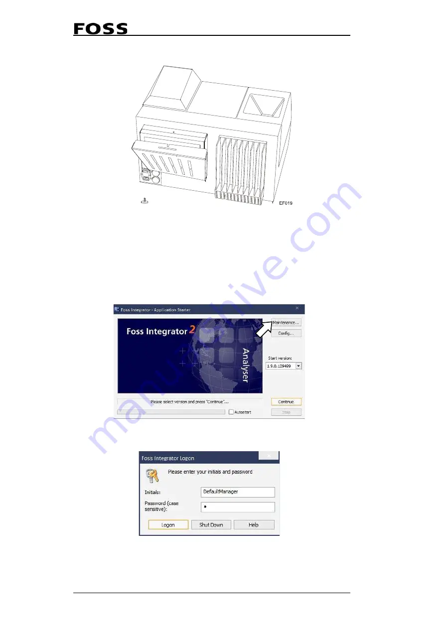
Fig. 5:9  Replacement of filter

3.

Replace the filter and re-assemble in reverse order.

5.1.7

Software Maintenance

Since the analysis generates much data, some care should be taken to the computer 
system. Results can be saved on a network drive, but on a weekly basis it is 
recommended to make a backup and cleanup the database.

1.

In the first window, select 

Maintenance

.

Fig. 5:10  

2.

Log in with your user name and password.

Fig. 5:11  

Summary of Contents for EyeFoss

Page 1: ...Copyright 2010 All rights reserved FOSS Analytical A S Foss Allé 1 DK 3400 Hillerød Denmark Tel Int 45 7010 3370 Fax 45 7010 3371 E mail info foss dk EyeFoss User Manual 6007 2981 Rev 10 ...

Page 2: ... 2010 06 22 First edition 2 2013 07 12 General update 3 2014 11 20 Genereal update 4 2015 01 10 Update of safety information 5 2015 12 07 General update 6 2015 12 21 New part number Safety chapters moved to Safety Manual 6007 2939 7 2016 04 12 Legal Data and PC Requirements updated 8 2016 12 09 Updated to reflect Foss Integrator version 2 Various changes 9 2017 07 01 Update of section 4 7 and 8 4 ...

Page 3: ...1 2 2 Image Analysis 2 1 2 3 System Description 2 3 2 3 1 General Description 2 3 2 3 2 System Overview 2 4 2 3 3 Functional Description 2 4 2 3 4 Start Button 2 5 2 3 5 A Kernel s Way Through an Analysis 2 6 2 3 6 Protection Cap 2 7 2 4 EyeFoss Software 2 8 3 Installation 3 1 4 Operating Instructions 4 1 4 1 Getting Started 4 1 4 2 Foss Integrator Start up 4 1 4 3 Installing a License 4 2 4 4 Imp...

Page 4: ...eUI 4 44 4 13 3 Closing SimpleUI 4 45 5 Maintenance 5 1 5 1 EyeFoss Maintenance 5 1 5 1 1 General 5 1 5 1 2 Cleaning replacement of Conveyor Belt 5 1 5 1 3 Cleaning Replacement of Belt Brush 5 3 5 1 4 Cleaning of Anti Static Brush 5 4 5 1 5 Replacement of Fuses 5 4 5 1 6 Replacement of Filter 5 5 5 1 7 Software Maintenance 5 6 5 2 FOSS Service Visit 5 8 6 Troubleshooting 6 1 6 1 Foss Integrator Tr...

Page 5: ...EyeFoss User Manual 6007 2981 Rev 10 8 3 Performance Data 8 2 8 4 Legal Data 8 2 8 5 PC Requirements 8 2 ...

Page 6: ...EyeFoss User Manual 6007 2981 Rev 10 ...

Page 7: ...der to find out the nature of the potential hazard please consult this manual in all cases where this symbol is used Warning Unpacking assembly and installation of the instrument should be performed by a FOSS authorised service engineer Warning The instrument is NOT to be operated in atmospheres which could constitute an explosion risk Symbol Description General hazard Electrical shock hazard Hot ...

Page 8: ...leaning the bottom of the feeder 1 2 2 Laser The EyeFoss is a Class I laser product and contains a laser The laser is totally shielded by the cabinet and there is no risk of laser radiation during normal use The embedded laser is a Class 3B laser with the specifications Max output of laser 25 mW Led wavelength 658 nm Warning Use of controls or adjustments or performance of procedures other than th...

Page 9: ...pment Connecting equipment that is not CE approved may cause EMC incompatibility and thereby affect the function of the instrument and other equipment Caution The system may only be repaired by personnel certified by FOSS FOSS recommends the use of original FOSS spare parts If spare parts from other are used the warranty no longer applies Caution If an ESD cap is provided it should be mounted on a...

Page 10: ...chase order together with the invoice or in the contract with the FOSS representative and only apply if the Customer User has followed all written instructions and documentation from FOSS regarding the product the product has been installed maintained adjusted and calibrated according to all descriptions and recommendations in the documentation the product has not been used for purposes other than...

Page 11: ...on 3 The name of the author may not be used to endorse or promote products derived from this software without specific prior written permission This software is provided by the author as is and any express or implied warranties including but not limited to the implied warranties of merchantability and fitness for a particular purpose are disclaimed In no event shall the author be liable for any di...

Page 12: ...EyeFoss 1 6 User Manual 6007 2981 Rev 10 ...

Page 13: ...d with various accessories such as sieves and scales this has provided information for different grading methods An accurate and consistent visual inspection and a correct and objective evaluation require long experience as well as a deep knowledge Because of that the grain industry has awaited a product that is able to perform reliable grain inspections in a consistent rapid cost effective and ob...

Page 14: ...EyeFoss 2 2 User Manual 6007 2981 Rev 10 Fig 2 1 EyeFoss 1 LED On Off 5 Drawer 2 Hopper 6 Belt brush 3 Feeder Unit 7 Camera Unit 4 Conveyor belt 8 Start button ...

Page 15: ...for sample preparation A physical and digital kernel separation ensures that most of the images will be useful for the assessment The analysis time from the time the start button is pressed until the result is displayed is two to three minutes for a standard sample The result which is calculated by Foss Integrator is displayed on the screen of the connected PC and may be printed if a printer is co...

Page 16: ...nveyor belt As the sample is brought forward by the belt the camera 4 continuously takes pictures of all kernels The camera unit consists of a line scan camera for image reproduction and a 3D laser for determination of physical parameters length height volume Images are processed by the internal processor also called prediction engine 5 and the final results are displayed on the external PC 6 Afte...

Page 17: ... kernels to be analysed can be set in the software If the sample volume poured into the feeder exceeds this limit the feeder and conveyor belt will move the excess sample to the collection drawer at a faster pace before the actual measurement starts Fixed Volume Sample Intake volume can be set to a specific value for a product This can be done when setting up a product which is described in setion...

Page 18: ...hen sent to the internal prediction engine were they are evaluated The camera takes pictures of each kernel on the conveyor belt which passes by the camera unit The camera unit consists of diodes that transmit light in six different wavelengths in the range from 405 to 850 nm Pour sample Camera Camera Images Result Evaluation Pour the sample into the hopper of the instrument UV Blue Green Orange R...

Page 19: ...ing Make sure that there is no gap between the protection cap and the metal sheet by securing the screw as the laser reflection can be hazardous to the operator Fig 2 6 The protection cap must close the gap 1 Securing screw 2 Protection cap 3 No gap here Ef025a 1 2 3 ...

Page 20: ...via the external PC and the program Foss Integrator FI For information on how to use this program see chapter 4 Operating Instructions User Interface For daily work the FI will start up with the Report window Fig 2 7 Dialogue box 1 Products 2 Sample Results 3 Start Stop 4 Online Help 5 Print ...

Page 21: ...he instrument should be performed by a FOSS authorised service engineer Caution The air circulation around the cooling flange must not be inhibited Leave uncovered with sufficient space for air circulation at all times For information about pre installation please refer to the Site Preparation Check List ...

Page 22: ...EyeFoss 3 2 User Manual 6007 2981 Rev 10 ...

Page 23: ... toolbar This will give you two options Either general help or help about the current view The F1 key can also be used to access help to the current view Note Foss Integrator is also used for other instruments so some images and products shown in the help files may not be related to image analysis or grain 4 2 Foss Integrator Start up 1 Click the icon on the desktop to open the Application Starter...

Page 24: ...an be changed by setting up a new user see section 4 11 Fig 4 3 Different parts of Foss Integrator can be accessed from the Window menu in the toolbar 4 3 Installing a License A license must be installed to run Foss Integrator and the calibrations 1 Click the Maintenance in the Application Starter window Fig 4 4 2 Log in with your credentials Fig 4 5 ...

Page 25: ...Manual 6007 2981 Rev 10 4 3 3 Click on Licenses Fig 4 6 This will open the window License Registration where you can see the licenses that are already installed 4 Click on the Add button to add new licenses Fig 4 7 ...

Page 26: ...ction Model Prediction models can be copied directly to the following directory if the directory doesn t exist simply create it C FOSS FossIntegrator PredictionModels or they can downloaded through Mosaic Once the prediction models have been copied to this directory start Foss Integrator Below is described how to import a prediction model locally 1 Go to Foss Integrator Settings and select Predict...

Page 27: ...1 Rev 10 4 5 2 Click on New Fig 4 10 3 Select Instrument in the drop down menu Type and select the prediction model that you want to import Fig 4 11 4 Click OK and the prediction model will synchronise with the instrument Fig 4 12 ...

Page 28: ...ttings window and click on Properties Fig 4 13 A new window appears with a number of tabs The most important tabs are Image Transfer and Slope and Intercept Here is it possible to select what has to be transferred saved and make changes to slope and intercept on the predictions Fig 4 14 Image Transfer tab ...

Page 29: ...d unit for the result 6 Click OK to save any changes and close the Prediction Model Settings window 4 5 Setting Up a Product To set up a product a prediction model must first be in made and set up see above 1 In the Foss Integrator window select Product Settings Fig 4 16 2 Click in the area to the left in the Product Settings window ...

Page 30: ... the product will already be here under the Network tab Fig 4 17 4 Enter a name and a description and click OK Fig 4 18 5 Click the Edit button next to Job types pos 1 in Fig 4 19 6 Select the proper job type pos 2 in Fig 4 19 in the popup window and click OK pos 3 Fig 4 19 Click Edit and select job type 1 2 3 ...

Page 31: ...election of Normal Normal Single Kernel and Calibration 7 Click the button Change under Icon 8 Select an icon for the product and click Open Fig 4 20 Select icon 9 Select Released for routine analysis under Status Fig 4 21 10 Open the product in the left part of the window and select Prediction models ...

Page 32: ...7 2981 Rev 10 11 Click Add in the menu at the bottom Fig 4 22 12 Select the prediction model s that you want and click OK Fig 4 23 The other options now become selectable on the lower part of the window 13 Click Secondary Fig 4 24 ...

Page 33: ... are displayed If you don t select any here they will not appear in the result view The Product Settings window will now look like Fig 4 26 below 15 Click OK to finish Fig 4 26 This product can now be found in the results view and be used for analysis To link this to a Quick job see section 4 6 step 11 Here use Simple instead of Advanced Otherwise the same procedure can be used ...

Page 34: ... 1 Go to Foss Integrator Settings and select Product Settings Fig 4 27 2 Click Edit under to Job types in the centre of the Product Settings window 3 Select Normal Single Kernal and none of the others 4 Click OK Fig 4 28 5 Back in the Product Settings window click Prediction Models and then Add ...

Page 35: ...4 29 6 Select all model types The other options now become selectable on the lower part 7 Click Secondary Fig 4 30 8 Select all the secondary prediction models in the popup window Fig 4 31 9 Click OK and return to the Foss Integrator Results window ...

Page 36: ...yeFoss 4 14 User Manual 6007 2981 Rev 10 10 Click on the Create quick job Fig 4 32 11 Select Advanced and click OK Fig 4 33 12 Select the job that was created earlier and give it a suitable name Fig 4 34 ...

Page 37: ...odel to the PC Prediction models can be copied directly to the following directory if it doesn t exist simply create it C FossIntegratorData PredictionModels or they can downloaded through Mosaic As no prediction model is used during the Zero setting any prediction model will be fine but there must be a prediction model and it must be set up in the correct way 1 Go to Foss Integrator Settings and ...

Page 38: ...e Zero and add a short description Fig 4 37 4 Click Edit next to Job types in the middle of the window 5 Select job type Zero setting and click OK Fig 4 38 6 Click the button Change under Icon 7 Select an icon for the product and click Open Fig 4 39 Select icon ...

Page 39: ... button to add a prediction model Fig 4 40 9 Select a prediction model and click OK It can be any prediction model since it is not used for the calibration However a prediction model must exist to be able to run it Fig 4 41 10 Click OK and return to the Foss Integrator Results window ...

Page 40: ...ev 10 11 Click on the option Create quick job Fig 4 42 12 Select Advanced and click OK If you are making a normal Quick job then select Simple instead Fig 4 43 13 In the Quick job Creation Advanced window and tick the check box Auto start ...

Page 41: ...s a verification of the instruments performance and quality It can be done either manually or automatically recommended Note If the automatic self test is chosen only errors in the self test will be displayed not warnings Warnings will only be disaplyed if the self test is completed manually Below is described how to do it manually 1 Go to the Diagnostic view in Foss Integrator and right click on ...

Page 42: ... test again and make a note of every error and contact a FOSS service engineer 4 7 1 Viewing or Printing the Diagnostic Report 1 Go to the menu Diagnostics and select Log files 2 Select Prediction PC to open a window with all diagnostic reports see Fig 4 48 3 Double click on the latest PDF file to open the diagnostics report In the report can you then see the warnings and errors depending on the p...

Page 43: ...followed by either Pass or Fail for example Diag_2017 05 02 22 10 58_8388616_13917861_Pass pdf see Fig 4 48 above This way it is easy to find the latest one and see if it has passed or failed The front page shows the Instrument ID the software version for the Measurement Engine ME and the name of the corresponding xml file The xml file can be used for further troubleshooting Fig 4 49 Cover page of...

Page 44: ...t of dirt on the belt It is common to get a warning that disappears on the next diagnostic If there is an error make a re run of the diagnostics Fig 4 50 Upper part of the summary table showing belt measurements 2D calibration targets The 2D calibration targets contain the diagnostics result based on the 2D calibration target measurements The 2D Calibration target measurements are used to verify t...

Page 45: ... job with multiple sample in one setting Both scenarios are described below 4 8 1 Single Sample The instrument must be in Standby mode before any samples can be analysed 1 Click the orange Play button to put the instrument in Standby mode Fig 4 52 2 Pour in a sample in the funnel and double click on the application you want to run in this example Barley BA_g08_v22_g02 Fig 4 53 The analysis will no...

Page 46: ...k on the box next to the sample ID see figure below Fig 4 55 4 Enter a sample id in the Sample ID area in the window that appears and click OK Fig 4 56 There are also other options in this window but none of them can be edited They are only for information ...

Page 47: ...strument can be used to start the analysis This method is more simple if many analyses are to be done using the same product 1 Right click in the Jobs area 2 Click on New Job Alternatively press the F2 key Fig 4 57 The window Sample Registration will appear 3 Go to the Advanced tab Here you can select the product and job type usually Normal 4 Enter the number of analysis in the Total field Fig 4 5...

Page 48: ...on on the instrument When a sample is ready the instrument will ask for the next sample Fig 4 59 If nothing happens for five minutes the window will close It is still possible to start the analysis with the start button on the instrument When the results are ready they will be shown in the Results view as below Fig 4 60 A Sample Id can be entered by double clicking in the box in the ID column as d...

Page 49: ...s ready a box for the sample id will appear in the result window 1 Double click in the box under ID Fig 4 61 2 Enter a sample id in the Sample ID area in the window that appears Fig 4 62 There are also other options in this window but none of them can be edited They are only for information ...

Page 50: ... Usually images will not be saved since each sample takes up a lot of disk space Below is described how to export the results without images 1 Click on the printer icon in the upper left corner for quick printing Fig 4 63 2 Select which template to use Fig 4 64 The next dialogue is a normal print dialogue Export as CSV Files Results can also be exported as CSV files 1 Right click on the sample 2 S...

Page 51: ...EyeFoss User Manual 6007 2981 Rev 10 4 29 3 Select a CSV file and results Fig 4 65 Export as CSX ...

Page 52: ...s 1 Click on Report Profile Settings in the Foss Integrator window if you want to use other templates Fig 4 66 This will open the Report Profile Settings window 2 Click New to make a new report profile Fig 4 67 3 Fill in name description and title and click Next Fig 4 68 ...

Page 53: ...EyeFoss User Manual 6007 2981 Rev 10 4 31 4 Click Add to get access to the prediction models you can choose Fig 4 69 5 Select the prediction model it should be active for and click OK Fig 4 70 ...

Page 54: ...EyeFoss 4 32 User Manual 6007 2981 Rev 10 6 Click Secondary to get access to selecting secondary models Fig 4 71 7 Select the secondary models you wish to use and click OK Fig 4 72 ...

Page 55: ...2981 Rev 10 4 33 8 Select one of the available reports in the Report template dropdown list and click Next If you need other formats please contact FOSS Fig 4 73 9 Select an output format for the report and click Next Fig 4 74 ...

Page 56: ...oss 4 34 User Manual 6007 2981 Rev 10 10 Select an installed printer in dropdown list Fig 4 75 11 Click on Finish to return to the initial screen Fig 4 76 12 Click OK and the report profile is ready for use ...

Page 57: ... Manual 6007 2981 Rev 10 4 35 13 The selected results will be printed so it can be either one or multiple results Fig 4 77 4 11 Creating a New User 1 Go to Foss Integrator Settings and select User Manager Fig 4 78 ...

Page 58: ...eFoss 4 36 User Manual 6007 2981 Rev 10 This will open a the User Manager window Fig 4 79 User Manager main window 2 Right click on Users and select New Fig 4 80 This will open the User properties window ...

Page 59: ...n information about the user Leave Member of empty for now Fig 4 81 User Properties window 4 Click OK 5 Right click on Operators under Groups and select Add member to add the user to a group Fig 4 82 This will open the Group properties Operators window ...

Page 60: ...can be set up either through Mosaic or locally directly in Foss Integrator Always use the same way to set up new products and calibrations If both are used it can create errors and problems because duplicated calibrations are not permitted The use of Mosaic is not described here Either use help files in Mosaic or a FOSS training course for help and education on how to use the Mosaic network tool ...

Page 61: ...39 4 12 1 Mosaic Settings 1 Go to Foss Integrator Settings and select the Mosaic synchronisation Fig 4 85 This will open the Mosaic Synchronisation Already Connected to Mosaic 1 Clicking the Sync button to make a new synchronisation Fig 4 86 ...

Page 62: ...al 6007 2981 Rev 10 The Synchronisation Log will then be updated Fig 4 87 Not Connected to Mosaic 1 Go to the Settings tab to set up the synchronisation for the first time Fig 4 88 Mosaic Synchronisation window not filled in ...

Page 63: ...he section Check for update from Mosaic if you want to enable automatic synchronisation within a certain period and fill out the date fields next to Reference time see Fig 4 89 below Fig 4 89 Mosaic synchronisation window filled in 4 You can choose to tick Skip upload of normal samples under General settings Large amounts of date are sent if images are saved see Fig 4 89 Try to avoid updates with ...

Page 64: ... SimpleUI it is not possible to rename the Sample ID nor to see previously analysed samples 4 13 1 Launching SimpleUI 1 Start Foss Integrator by clicking the icon on the desktop For details about the start up of Foss Integrator see section 4 2 Fig 4 90 2 Start SimpleUI by clicking the icon on the desktop Fig 4 91 3 In Foss Integrator go to the Window menu and select Diagnostics Fig 4 92 ...

Page 65: ...e exact name of the SimpleUI is specified during the installation of EyeFoss and can vary from instrument to instrument 6 Click Connect Fig 4 93 LIMS monitor 1 tab 7 Tick Remote control active in the bottom of the tab Fig 4 94 Note If Remote control active is greyed out disable LIMS connection on the Main LIMS monitor tab and try again ...

Page 66: ...monitor tab 9 Click on Enable LIMS Fig 4 95 Main LIMS monitor tab 10 Go to SimpleUI interface and click OK SimpleUI can now be used to control EyeFoss 4 13 2 Using SimpleUI Fig 4 96 1 List of Quick Jobs 2 Errors warnings 3 Quick Jobs 4 Start analysis EF 028a 1 2 3 4 ...

Page 67: ...tes to complete it from Foss Integrator it will take approximately two minutes The error warning icon pos 2 in Fig 4 96 flashes red yellow when an event occurs which requires attentions To see the error warning message go to Foss Integrator and select Work Session Events in the Window menu in Foss Integrator 4 13 3 Closing SimpleUI 1 When you exit SimpleUI disable the LIMS connection from Foss Int...

Page 68: ...EyeFoss 4 46 User Manual 6007 2981 Rev 10 ...

Page 69: ...r inside the instrument Daily A selftest should be done every morning the simple way to do that is to set it for automatic selftest ZERO should be done at least once a day Weekly Run the Clean procedure It can be found in the Reports view under Maintenance Fig 5 1 Simply follow the instructions on the screen 5 1 2 Cleaning replacement of Conveyor Belt Consider the belt to be a wear part The lastin...

Page 70: ...m box spanner to loosen the bolt and rotate the belt stretcher counter clockwise so the belt becomes loose Fig 5 3 Loosen the belt stretcher 4 Carefully pull the belt out towards you 5 Inspect the belt surface and look for spots If spots are found first try to brush them of 6 The belt needs to be scrubbed to remove ingrained dirt grime from it Simply washing it in soapy water will NOT clean it pro...

Page 71: ...sh is a consumable wear part It must be replaced when worn The time between replacements depends on the amount of samples and the cleanness of the samples When cleaning replacing the belt brush follow the steps below 1 Remove conveyor belt cover 2 Remove the thumb screws and slide out the brush Fig 5 5 Cleaning exchange of belt brush 3 Inspect the brush and if necessary clean it by soaking the bru...

Page 72: ...n be removed for easier access to the antistatic brush 3 Remove any kernels or parts of kernels stuck to the antistatic brush 4 Reassemble conveyor belt cover Fig 5 6 Note Replacement of anti static brush is part of the Preventive Maintenance Agreement PMA 5 1 5 Replacement of Fuses Hot Surface The cooling flange can reach a very high temperature Warning Before installing or replacing the fuses di...

Page 73: ...he T 4AL 250TP fuses in the fuse holder and gently put the holder back in place 5 1 6 Replacement of Filter The filter that is located on the rear of the instrument should be replaced regularly approximately once a year 1 Loosen the thumb screw on the top of the filter cover Fig 5 8 Replacement of filter 2 Tilt the filter cover outwards and pull the filter out ...

Page 74: ... Software Maintenance Since the analysis generates much data some care should be taken to the computer system Results can be saved on a network drive but on a weekly basis it is recommended to make a backup and cleanup the database 1 In the first window select Maintenance Fig 5 10 2 Log in with your user name and password Fig 5 11 ...

Page 75: ...EyeFoss User Manual 6007 2981 Rev 10 5 7 3 Backup and Restore are self explaining Cleanup will delete old results Fig 5 12 4 Click on Cleanup and older data will be delated Fig 5 13 ...

Page 76: ...nts are replaced before they are worn out and have a negative impact on more complex and expensive parts This will help prevent unexpected downtime and also ensure quality and consistency of results at the highest level Contact your local FOSS representative for yearly maintenance FOSS offers a wide range of local support products and training adapted to your market requirements Please contact the...

Page 77: ...t will direct you to help regarding the function that is currently active 6 1 1 At Startup If you try to start Foss Integrator when an instance is already running or if Foss Integrator was closed in unexpected way the following error message may appear Fig 6 1 6 1 2 Communication Problems If there is a problem to connect to the instrument it can look like shown below Fig 6 2 If it has worked befor...

Page 78: ...ription a window will popup with further information about the warning or error and a hint on how to solve the problem Fig 6 1 When an error occurs is it common that the analyser closes down and has to be restarted In the upper part of Foss Integrator you can see whether the analyser is running The blue indicator to the right has a red and a green light If it is red the instrument is offline Click...

Page 79: ...ction The status of the connection is visible in the notification area of the lower right corner of the PC screen Fig 6 5 No communication between PC and the instrument Check that a network cable is connected between the units and that the EyeFoss is switched on The PC is trying to establish contact with the EyeFoss this may take a couple of minutes Communication is established and OK between the ...

Page 80: ...n the PC e g Firewall restrictions TCP IP protocol settings etc Normally this is corrected by the FOSS representative during the first installation Please contact a FOSS representative if communication problems occur e g after installation of a new PC or after changes to the PC s network configuration ...

Page 81: ...EyeFoss User Manual 6007 2981 Rev 10 7 1 7 Parts Accessories and Consumables See the Owner s Guide distribured via USB ...

Page 82: ...EyeFoss 7 2 User Manual 6007 2981 Rev 10 ...

Page 83: ... AC frequency 50 60 Hz Class 1 earthed Power cable 115V UL CSA C13 connector 10 A 125 V UL CSA approved 3 wire cable with protection ground SVT 18 AWG UL CSA approved 230V CE C13 connector 10 A 250 V CE VDE S Approved 3 wire cable 0 75mm2 H 05 VV F CE VDE S Approved Ambient temperature 5 42 C Storage temperature 20 C to 70 C Ambient humidity 93 RH Operation Indoor use Altitude Up to 2000 m Transie...

Page 84: ...2 EC RoHS Directive 2002 95 EC WEEE Directive 2012 19 EU REACH Directive 1907 2006 EC 8 5 PC Requirements Windows 7 64 bit Two 1 gigabit network connections one for the instrument and one for LAN Intel Core i5 CPU or better 8 GB RAM or more EyeFoss Measurement mode Reflectance Imagingand volumetric scanning Illumination type Diffused light from high power light emitting diodes Illumination wavelen...

Reviews: