


24
WWW.FORNEYIND.COM
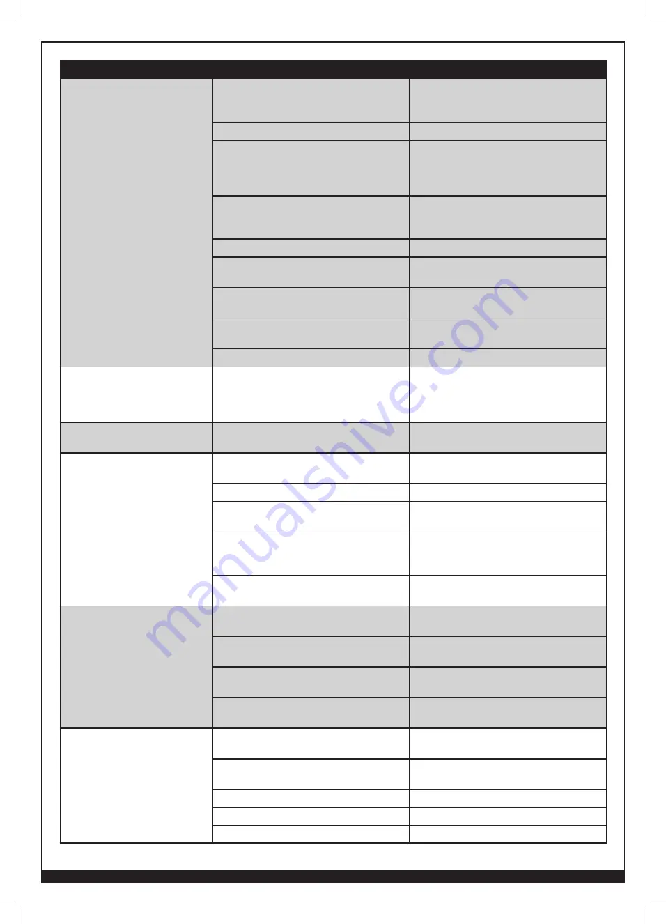
PROBLEM
POSSIBLE CAUSE
POSSIBLE SOLUTION
No wire feed.
Wire feed tension too high.
Slowly remove wire feed tension while
depressing the spool gun trigger. Use as little
tension as necessary for smooth operation.
Remote / local switch set to local.
Ensure switch is set to “Remote”.
Wire feed tension too low.
If drive roller is turning but wire is not
feeding, release trigger and apply more
tension. Use as little tension as necessary for
smooth operation.
Welding wire fused to contact tip.
Attempt to pull wire out of front of contact tip
with pliers. If necessary, remove contact tip
and cut welding wire. Discard contact tip.
Wire feed speed set too low.
Increase wire feed speed.
Contact tip is too small for the wire diameter. Always use a contact tip that is one size
larger than the welding wire.
Using the wrong drive roll groove.
Ensure the top groove on the drive roller
corresponds to the welding wire diameter.
Wire is tangled on spool.
Try to untangle spool. If necessary, discard
spool.
Empty wire spool.
Replace wire spool.
Wire feed speed slows down.
Welder is in throttled back-feed mode.
If the Forney welding machine does not detect
an arc after a few seconds with the trigger
depressed, the wire feed speed is automatically
throttled back.
Delay between trigger and wire
feed.
Slope set too high.
Turn slope of motor down. (Only applies to
models that have adjustable slope.)
Birdsnesting.
Wire is not aligned with torch neck inlet guide. Ensure that the welding wire is aligned to flow
smoothly onto the torch neck inlet guide.
Wire feed too low.
Increase wire feed speed.
Tension too low / too high.
Use as little tension as necessary for smooth
operation.
Welding wire is fused to contact tip.
Attempt to pull wire out of front of contact tip
with pliers. If necessary, remove contact tip
and cut welding wire. Discard contact tip.
Contact tip is too small for wire diameter.
Always use a contact tip that is one size
larger than the welding wire.
No gas flow.
Machine is in wrong process (SMAW or
GTAW).
Ensure machine is set to MIG mode (manual
2T, manual 4T, synergic 2T, synergic 4T).
Gas cylinder is closed.
Ensure that gas cylinder is fully opened. Set
flowmeter to 25-30CFH.
Gas cylinder is empty.
Ensure that the gas cylinder is not empty. If
necessary, replace gas cylinder.
Blockage in tank valve.
Remove regulator from tank. Purge tank to
clear blockage.
Soot covered / discolored welds.
Wrong shielding gas.
Always use 100% pure argon shielding gas
when welding aluminum.
“Pulling” arc instead of “pushing” arc.
When welding aluminum, push the nozzle in
the direction of the weld rather than pulling.
Gas connection loose; sucking in atmosphere.
Ensure all gas fittings are tight.
Gas flow too low.
Increase gas flow.
Gas flow too high.
Decrease gas flow.


