Formax 3950 Series, Operator'S Manual
The Formax 3950 Series Operator's Manual is available for free download on our website. This comprehensive manual provides detailed instructions and information on how to operate and maintain your Formax 3950 Series product. Get your manual today at manualshive.com and ensure optimal performance of your equipment.
Share
Download


Reviews:
No comments
Related manuals for 3950 Series
Perfect Binder B1
Brand: Canon Pages: 154
Clixx'Pixx DoublePageMaker
Brand: ProMaxX Pages: 2
FD 160
Brand: Formax Pages: 13
Cardmac Pro
Brand: Akiles Pages: 21
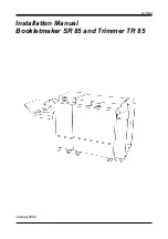
SR 85
Brand: Plockmatic Pages: 20
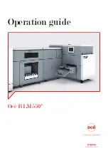
Oce BLM550+
Brand: Canon Pages: 138
Perfect Binder B1
Brand: Canon Pages: 274

Perfect Binder D1
Brand: Canon Pages: 28
Smart Dedicated Design BLM300C
Brand: Canon Pages: 36
Two-Knife Booklet Trimmer-A1
Brand: Canon Pages: 155
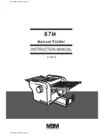
87m
Brand: MBM Pages: 20

307A
Brand: MBM Pages: 28
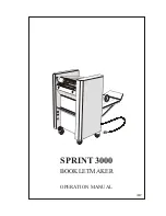
SPRINT 3000
Brand: MBM Pages: 17
Spine Pro
Brand: MBM Pages: 17
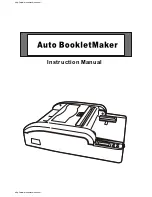
BO0841 Autobook
Brand: MBM Pages: 21

StitchFold
Brand: MBM Pages: 27
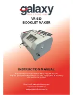
VR-930
Brand: Galaxy Print Finishing Pages: 15
87m
Brand: MBM Pages: 21


