Canon Perfect Binder B1, Troubleshooting Manual
The Canon Perfect Binder B1 is a cutting-edge binding machine designed to deliver flawless results. Easily troubleshoot any issues by referring to the comprehensive Troubleshooting Manual, available for free download on our website. Get expert assistance to optimize your binder's performance and achieve professional-quality results every time.
Share
Download


Reviews:
No comments
Related manuals for Perfect Binder B1
Perfect Binder B1
Brand: Canon Pages: 154
Clixx'Pixx DoublePageMaker
Brand: ProMaxX Pages: 2
FD 160
Brand: Formax Pages: 13
Cardmac Pro
Brand: Akiles Pages: 21
SR 85
Brand: Plockmatic Pages: 20
Oce BLM550+
Brand: Canon Pages: 138
Perfect Binder D1
Brand: Canon Pages: 28
Smart Dedicated Design BLM300C
Brand: Canon Pages: 36
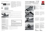
Two-Knife Booklet Trimmer-A1
Brand: Canon Pages: 155
87m
Brand: MBM Pages: 20

307A
Brand: MBM Pages: 28
SPRINT 3000
Brand: MBM Pages: 17
Spine Pro
Brand: MBM Pages: 17
BO0841 Autobook
Brand: MBM Pages: 21
StitchFold
Brand: MBM Pages: 27
VR-930
Brand: Galaxy Print Finishing Pages: 15
87m
Brand: MBM Pages: 21
BOOKIT
Brand: Galaxy Pages: 3


