background image

Note:

When the mirrors are

operated often during a short period
of time, the system may become
inoperable for a period of time to
prevent damage due to overheating.

Reverse mirror dipping

Depending on the selected mirror
position (

A

 or 

C

), the relevant exterior

mirror will dip whenever you select
reverse gear, giving you a view of the
kerb.

When you first use this feature, the
mirrors will dip to a preset position.
You can programme the degree of
dipping using the following sequence:

Note:

You can disable this feature

by leaving the electric exterior mirror
selector switch in position 

B

.

The exterior mirrors will return to the
original position:

If the vehicle speed exceeds 10
km/h (6 mph).

Approximately 10 seconds after
reverse gear has been
disengaged.

If the electric exterior mirror
selector switch is returned to
position 

B

.

Passive setting

1. Turn the ignition on. Do not start

the engine.

2. Select the desired exterior mirror

(

A

 or 

C

).

3. Select reverse gear, the selected

exterior mirror will adjust to a
preset position.

4. Adjust the mirrors to the required

dipped position.

5. Disengage reverse gear.

The settings will be stored
automatically.

Active setting

1. Turn the ignition on. Do not start

the engine.

2. Select the desired exterior mirror

(

A

 or 

C

).

3. Select reverse gear, the selected

exterior mirror will adjust to a
preset position.

4. Adjust the mirror to the required

dipped position.

5. Press and hold the desired

pre-set button until a single chime
sounds to confirm.  See 

Memory

function

 (page 133).

INTERIOR MIRROR

E71272

Dip the mirror to reduce glare when
driving at night.

77

Windows and mirrors

Summary of Contents for Mondeo 2007

Page 1: ...Feel the difference FordMondeo Owner s handbook ...

Page 2: ...rved to change specifications design or equipment at any time without notice and without incurring any obligations This publication or part thereof may not be reproduced nor translated without our approval Errors and omissions excepted Ford Motor Company 2007 All rights reserved Part number 8S7J 19A321 DA CG3536en 06 2007 20070727130405 ...

Page 3: ...equencies 34 Programming the remote control 34 Changing the remote control battery 34 Locks Locking and unlocking 36 Global opening and closing 38 Keyless entry 40 Engine immobiliser Principle of operation 44 Coded keys 44 Arming the engine immobiliser 44 Disarming the engine immobiliser 44 Alarm Principle of operation 45 Arming the alarm 47 Disarming the alarm 47 Steering wheel Adjusting the stee...

Page 4: ...f operation 109 Air vents 109 Manual climate control 110 Automatic climate control 113 Heated windows and mirrors 116 Auxiliary heater 116 Electric sunroof 120 Seats Sitting in the correct position 124 Manual seats 124 Electric seats 125 Head restraints 127 Rear seats 127 Heated seats 128 Ventilated seats 129 Convenience features Sun blinds 130 Instrument lighting dimmer 130 Clock 130 Cigar lighte...

Page 5: ...rinciple of operation 155 Using HLA 155 Active suspension Principle of operation 158 Using active suspension 158 Parking aid Principle of operation 159 Using the parking aid 159 Cruise control Principle of operation 161 Using cruise control 161 Adaptive cruise control ACC Principle of operation 163 Using ACC 165 Forward alert function 168 Load carrying General information 170 Luggage anchor points...

Page 6: ...Ci DW Diesel 210 Engine compartment overview 2 2L Duratorq TDCi DW Diesel 211 Engine oil dipstick 1 6L Duratec 16V Ti VCT Sigma 212 Engine oil dipstick 2 0L Duratec HE MI4 2 3L Duratec HE MI4 212 Engine oil dipstick 2 5L Duratec ST VI5 213 Engine oil dipstick 1 8L Duratorq TDCi Kent Diesel 213 Engine oil dipstick 2 0L Duratorq TDCi DW Diesel 2 2L Duratorq TDCi DW Diesel 213 Engine oil check 213 En...

Page 7: ... 243 Telephone General information 252 Telephone setup 252 Bluetooth setup 254 Telephone controls 255 Using the telephone Vehicles Without Navigation System 256 Using the telephone Travel Pilot EX 259 Voice control Principle of operation 262 Using voice control 263 Audio unit commands 263 Telephone commands 268 Navigation system commands 273 Climate control commands 273 Appendices Electromagnetic ...

Page 8: ...6 ...

Page 9: ...sk damaging your vehicle if you do not follow the instructions highlighted by the caution symbol Symbols on your vehicle When you see these symbols read and follow the relevant instructions in this handbook before touching or attempting adjustment of any kind PARTS AND ACCESSORIES Now you can be sure that your Ford parts are Ford parts Your Ford has been built to the highest standards using high q...

Page 10: ...s to be repaired look for the clearly visible Ford branding and make sure that only Ford Original Parts have been used Look for the Ford logo on the following parts Sheet metal Bonnet Doors Luggage compartment lid or tailgate E88678 Bumper and radiator grille Radiator grille Front and rear bumper E88505 Exterior mirror E88506 Glass Rear window Side glass Windscreen 8 Introduction ...

Page 11: ...E88507 Lighting Rear lamps Headlamp E88508 9 Introduction ...

Page 12: ...QUICK START Instrument panel overview left hand drive A I J K L M C B G H F E D V O N U T S R Q P E87719 10 Quick start ...

Page 13: ...e Direction indicators page 61 Telephone control buttons See Telephone controls page 255 Voice control buttons See Using voice control page 263 C Instrument cluster See Gauges page 79 D Information display controls See Information displays page 85 E Wiper lever See Windscreen wipers page 51 F Start Button See Keyless starting page 136 G Audio or navigation unit See separate handbook H 11 Quick sta...

Page 14: ...al climate control page 110 See Automatic climate control page 113 N Cigar lighter See Cigar lighter page 130 O Ignition switch See Ignition switch page 136 P Cruise control switches See Using cruise control page 161 Adaptive cruise control switches See Using ACC page 165 Q Steering wheel adjustment lever See Adjusting the steering wheel page 49 R Horn S Cruise control switches See Using cruise co...

Page 15: ...be located within one of the three external detection ranges Unlocking the vehicle E78278 Pull a door handle to unlock all the doors and the luggage compartment lid and disarm the alarm Locking the vehicle E87384 E87435 See Keyless entry page 40 Keyless starting E85766 13 Quick start ...

Page 16: ... engine page 136 Adjusting the steering wheel WARNING Never adjust the steering wheel when the vehicle is moving E71221 See Adjusting the steering wheel page 49 Electric folding mirrors E72623 See Electric exterior mirrors page 76 Information displays E70499 Use the arrow buttons to navigate through the menus and press OK to make a selection See Information displays page 85 14 Quick start ...

Page 17: ...ghting control page 56 Direction indicators E70727 Note Tap the lever up or down to make the direction indicators flash only three times Autowipers B C D A E70696 Single wipe A Autowipers B Normal wipe C High speed wipe D E70316 A B High sensitivity A Low sensitivity B See Autowipers page 51 15 Quick start ...

Page 18: ...Vehicles with keyless starting press the start button 2 Adjust the seat and exterior mirrors to the desired position 3 Press and hold the desired pre set button B for at least 3 seconds 4 A message will be shown in the display 5 A chime will sound to confirm See Memory function page 133 Manual climate control Heating the interior quickly E71377 Cooling the interior quickly E71381 Defrosting and de...

Page 19: ... control page 113 Selecting reverse gear Vehicles with a 6 speed transmission Vehicles with a petrol engine E75051 1 2 Vehicles with a diesel engine E75052 2 1 See Manual transmission page 147 Automatic transmission Selector lever positions E80836 S Park P Reverse R Neutral N 17 Quick start ...

Page 20: ... any residual fuel from the fuel pipe nozzle We recommend that you wait at least 10 seconds before removing the fuel pipe nozzle to allow any residual fuel to drain into the fuel tank E86613 Press the flap to open it Open the flap fully until it engages When you insert the fuel pipe nozzle a spring loaded inhibitor will open if the correct size nozzle is detected This will prevent filling up with ...

Page 21: ... child on your lap when the vehicle is moving Do not leave unattended children in your vehicle WARNINGS If your vehicle has been involved in an accident have the child restraints checked by properly trained technicians Note Mandatory use of child restraints varies from country to country A choice of ECE approved child restraints which have been specifically tested and approved for your vehicle are...

Page 22: ... back Do not use pillows books or towels to boost your child s height Make sure that your children sit in an upright position WARNINGS Secure children that weigh more than 15 kilogrammes but are less than 150 centimetres tall in a booster seat or a booster cushion Booster seat E70710 We recommend that you use a booster seat that combines a cushion with a backrest instead of a booster cushion only ...

Page 23: ...mmes 49 and 79 pounds CAUTION Remove the rear seat head restraint unless the child s head exceeds the top of the backrest See Head restraints page 127 Unlocking 1 2 E94860 Note Make sure that the locking mechanism is fully engaged 3 E94861 The raised seating position will allow you to position the shoulder strap of the adult seat belt over the centre of your child s shoulder and the lap strap tigh...

Page 24: ...pport leg on a second row seat make sure the support leg rests securely on the floor When using a forward facing child seat on a second row seat always remove the head restraint from that seat Note When using a child restraint on a front seat it may prove difficult to tighten the lap section of the seat belt without slack remaining If this is the case adjust the seatback to the fully upright posit...

Page 25: ...r use in this mass group However we recommend that you secure children in a government approved child restraint in the rear seat UF Suitable for universal category forward facing child restraints approved for use in this mass group However we recommend that you secure children in a government approved child restraint in the rear seat ISOFIX child restraints Mass group categories Seating positions ...

Page 26: ...p 0 In addition any semi universal ISOFIX child restraint may be used if indicated in the child seat manufacturers vehicle list As defined by ECE R16 Note When you are purchasing an ISOFIX restraint make sure that you know the correct mass group and ISOFIX size class for the intended seating locations Note Make sure that the top tether mechanism does not interfere with the luggage cover 24 Child s...

Page 27: ...n the child restraint that attach to anchor points on the outboard rear seats where the cushion and backrest meet Tether anchor points are fitted behind the outboard rear seats for child restraints with a top tether Top tether anchor points E87146 E93616 E93514 Attaching a child seat with top tethers WARNING Do not attach a tether strap to anything other than the correct tether anchor point Note W...

Page 28: ...Head restraints page 127 WARNING Make sure the top tether strap is not slack or twisted and is properly located on the anchor point 3 Route the tether strap to the anchor point WARNING Make sure that the seatback is secure and fully engaged in the catch 4 Push the seatback to the upright position E87145 5 Push the child seat back firmly to engage the ISOFIX lower anchor points 6 Tighten the tether...

Page 29: ...CHILD SAFETY LOCKS WARNING You cannot open the doors from inside if you have put the child safety locks on E73697 A B Lock A Unlock B 27 Child safety ...

Page 30: ...o not affix anything to or over the airbag covers Do not poke sharp objects into areas where airbags are fitted This could damage and adversely affect deployment of the airbags Use seat covers designed for seats with side airbags Have these fitted by a properly trained technician Note You will hear a loud bang and see a cloud of harmless powdery residue if an airbag deploys This is normal Note Onl...

Page 31: ... a lower deployment threshold than the front airbags During a minor collision it is possible that only the knee airbag deploys Side airbags E72658 Side airbags are fitted inside the seatback of the front seats A label indicates that side airbags are fitted to your vehicle The side airbags will deploy during significant lateral collisions Only the airbag on the side affected by the collision will d...

Page 32: ...icient distance between yourself and the steering wheel Only when you use the seat belt properly can it hold you in a position to achieve its optimum effect See Sitting in the correct position page 124 Never use a seat belt for more than one person Use the correct buckle for each seat belt Do not use a seat belt that is slack or twisted Do not wear thick clothing The seat belt must fit tightly aro...

Page 33: ... the belt Let it retract completely and smoothly SEAT BELT HEIGHT ADJUSTMENT E87511 Note Lifting the slider slightly while pressing the locking button makes it easier to release the locking mechanism To raise or lower press the locking button on the adjuster and move as necessary SEAT BELT REMINDER WARNING Do not sit on top of a fastened seat belt to prevent the seat belt reminder from coming on T...

Page 34: ...lts Deactivating the seat belt reminder See your dealer USING SEAT BELTS DURING PREGNANCY E68587 WARNING Position the seat belt correctly for your safety and that of your unborn child Do not use only the lap strap or the shoulder strap Position the lap strap comfortably across your hips and low beneath your pregnant abdomen Position the shoulder strap between your breasts above and to the side of ...

Page 35: ...p illuminates or flashes when you are driving this indicates a malfunction See Warning lamps and indicators page 81 Remove the child restraint and have the system checked immediately Disabling the passenger airbag A B E71312 Disabled A Enabled B Turn the switch to position A When you switch the ignition on check that the passenger airbag deactivation warning lamp illuminates Enabling the passenger...

Page 36: ...te You could unlock the doors if you press the buttons on the remote control unintentionally The operating range between your remote control and your vehicle varies depending on the environment PROGRAMMING THE REMOTE CONTROL You can programme a maximum of eight remote controls to use with your vehicle including any supplied with your vehicle Ask your dealer for instructions CHANGING THE REMOTE CON...

Page 37: ...rds 6 Assemble the two halves of the remote control 7 Install the key blade Remote control without a folding key blade E74386 1 Insert a screwdriver into the recess on the back of the key and remove the key blade 2 Release the retaining clips with the screwdriver and separate the two halves of the remote control CAUTION Do not touch the battery contacts or the printed circuit board with the screwd...

Page 38: ...side if you have double locked them E71961 Double locking is a theft protection feature that prevents someone from opening the doors from the inside You can only double lock the doors if they are all closed Locking and unlocking confirmation When you unlock the doors the direction indicators will flash once When you lock the doors the direction indicators will flash twice Note If your vehicle has ...

Page 39: ...h the remote control Press button B once Double locking the doors and the luggage compartment lid with the remote control Press button B twice within three seconds Locking and unlocking the doors from inside Front doors E71958 A B Lock all doors A Unlock all doors B Rear doors To lock the rear doors individually press button A and close the door when leaving the vehicle Luggage compartment lid Ope...

Page 40: ... unlocking function If the unlocking function is reprogrammed so that only the driver s door is unlocked See Programming the remote control page 34 note the following When you press the unlock button either all the doors are unlocked or only the driver s door is unlocked Pressing the unlock button again unlocks all the doors GLOBAL OPENING AND CLOSING You can also operate the electric windows with...

Page 41: ...e care when using global closing In an emergency press a button immediately to stop E71956 To close all the windows press and hold the lock button for at least three seconds Press any button again to stop the closing function The anti trap function is also active during global closing Vehicles with the key free system E78275 WARNING Take care when using global closing In an emergency press the but...

Page 42: ...the system will become inoperable for 30 seconds The passive entry system will not function if The passive key frequencies are jammed The passive key battery is flat Note If the passive entry system does not function you will need to use the key blade to lock and unlock your vehicle The keyless system allows the driver to operate the vehicle without the use of a key or remote control E78276 Passiv...

Page 43: ...ou to pull a door handle and check if the vehicle is locked When the delay period is over the doors can be opened again provided the passive key is within the respective detection range Luggage compartment lid Note The luggage compartment lid cannot be closed and will pop back up if the passive key is located inside the luggage compartment Note If a second valid passive key is located within the l...

Page 44: ...ocked All the other doors can be unlocked from inside the vehicle by pressing the unlock button next to the driver s door handle Doors can be unlocked individually by pulling the interior door handles on those doors If the front passenger door or one of the rear doors is the first door which is opened all the doors and the luggage compartment lid will be unlocked Disabled keys Any keys left inside...

Page 45: ...E78284 1 Slide the release slider in the direction of the arrow and pull out the key blade with your thumb 2 Remove the key blade and insert it into the lock Type 2 1 2 E87964 1 Carefully remove the cover 2 Remove the key blade and insert it into the lock 43 Locks ...

Page 46: ...umber from the tag provided with the original keys You can also obtain additional keys from your Ford Dealer ARMING THE ENGINE IMMOBILISER The engine immobiliser is armed automatically a short time after you have switched the ignition off DISARMING THE ENGINE IMMOBILISER The engine immobiliser is disarmed automatically when you switch the ignition on with a correctly coded key If the message Immob...

Page 47: ...p sounder The battery back up sounder is an extra alarm system which will sound a siren when the alarm is triggered It is armed directly when you lock the vehicle The sounder has its own battery and will sound an alarm siren even if someone disconnects the vehicle battery or the battery back up sounder itself Tilt sensors The tilt sensors detect if someone attempts to steal a wheel or tow the vehi...

Page 48: ...duced guard the interior and tilt sensors are deactivated when you arm the alarm Note You can set the alarm to reduced guard for the current ignition cycle only The next time you switch on the ignition the alarm will be reset to full guard Ask on Exit You can set the information display to ask you each time which level of guard you wish to set If you select Ask on Exit the message Reduced guard ap...

Page 49: ...ee Locks page 36 DISARMING THE ALARM Vehicles without keyless entry Perimeter alarm Disarm and silence the alarm by unlocking the doors with the key and switching the ignition on with a correctly coded key or unlocking the doors or the luggage compartment lid with the remote control Category one alarm Disarm and silence the alarm by unlocking the doors with the key and switching the ignition on wi...

Page 50: ...tegory one alarm Disarm and silence the alarm by unlocking the doors and switching the ignition on within 12 seconds or unlocking the doors or the luggage compartment lid with the remote control 48 Alarm ...

Page 51: ... E95178 3 E95179 WARNING Make sure that you fully engage the locking lever when returning it to its original position AUDIO CONTROL A C B D E E72288 Volume up A Seek up B Volume down C Seek down D Mode E Mode Press and hold the mode button to select the audio source Press the mode button to tune the radio to the next preset station play the next CD play the other side of a cassette tape 49 Steerin...

Page 52: ... button to tune the radio to the next station up or down the frequency band play the next or the previous CD track fast forward or rewind the cassette tape Press and hold a seek button to tune the radio up or down the frequency band seek through a CD track 50 Steering wheel ...

Page 53: ...ers may operate if dirt mist or flies hit the windscreen Replace the wiper blades as soon as they begin to leave bands of water and smears If you do not replace them the rain sensor will continue to detect water on the windscreen and the wipers will operate even though the majority of the windscreen is dry Fully defrost the windscreen in icy conditions before you switch autowipers on Switch autowi...

Page 54: ... sensitivity the wipers will operate if the sensor detects a small amount of water on the windscreen WINDSCREEN WASHERS WARNING Do not operate the windscreen washers for more than 10 seconds or when the reservoir is empty Note The washer jets are heated when the ignition is on E70776 REAR WINDOW WIPER AND WASHERS Intermittent wipe E70777 Reverse gear wipe The rear window wiper will operate automat...

Page 55: ... your fingers over the edge of the blade to check for roughness Clean the wiper blade lips with water applied with a soft sponge CHANGING THE WIPER BLADES Windscreen wiper blades CAUTIONS Set the windscreen wipers in the service position to change the wiper blades You can use the service position in winter to provide easier access to the wiper blades for freeing them from snow and ice The windscre...

Page 56: ...pers in the service position and lift the wiper arms E72899 1 2 1 Press the locking button 2 Remove the wiper blade Note Make sure that the wiper blade locks into place 3 Install in the reverse order Rear window wiper blades Changing the rear window wiper blades Estate 1 Lift the wiper arm 2 3 4 E86456 2 Position the wiper blade at right angles to the wiper arm 3 Disengage the wiper blade from the...

Page 57: ...tall in the reverse order Changing the rear window wiper blades 5 door 1 Lift the wiper arm E86457 2 3 2 Press the locking button 3 Remove the wiper blade Note Make sure that the wiper blade locks into place 4 Install in the reverse order 55 Wipers and washers ...

Page 58: ...ps will discharge the battery Switch off the ignition Both sides Set the lighting control to position B One side E75505 A B Right hand side A Left hand side B Main and dipped beam E70725 Pull the lever fully towards the steering wheel to switch between main and dipped beam Headlamp flasher Pull the lever slightly towards the steering wheel 56 Lighting ...

Page 59: ...ing the direction indicator lever towards the steering wheel again or by turning the ignition switch on AUTOLAMPS E70719 Note If you have switched autolamps on you can only switch the main beam on when autolamps has switched the headlamps on The headlamps will come on and go off automatically depending on the ambient light FRONT FOG LAMPS E70721 WARNING Only use the front fog lamps when visibility...

Page 60: ...s B You can adjust the level of the headlamp beams according to the vehicle load Recommended headlamp levelling switch positions Switch position Load in luggage compartment Load Second row seats Front seats 0 1 2 0 0 5 2 1 2 1 0 5 2 3 1 2 3 0 5 2 Max 1 3 1 2 4 1 5 2 Max 1 1 1 See Vehicle identification page 242 2 Vehicles with active suspension 58 Lighting ...

Page 61: ...egulations in the country for which your vehicle was originally built the hazard warning flashers may flash if you brake heavily E71943 For item location See Quick start page 10 ADAPTIVE FRONT LIGHTING SYSTEM AFS E72897 A B A B without AFS A with AFS B 59 Lighting ...

Page 62: ...you have switched on the daytime running lamps or when you have selected reverse gear A message will appear in the information display if the system malfunctions See Information messages page 99 The headlamps will move to a fixed central or dipped position Have the system checked as soon as possible Cornering lamps E72898 B A B A Headlamp beam A Cornering lamp beam B The cornering lamps illuminate...

Page 63: ...ck on switch on the ignition for a short time The courtesy lamp will also come on when you switch off the ignition It will go off automatically after a short time or when you start or restart the engine If you set the switch to position C with the ignition switch off the courtesy lamp will come on It will go off automatically after a short time to prevent the vehicle battery from discharging To sw...

Page 64: ...e vehicle battery from discharging To switch them back on switch on the ignition for a short time REMOVING A HEADLAMP WARNING Have Xenon bulbs changed by a trained technician There is a risk of electric shock 1 Open the bonnet See Opening and closing the bonnet page 203 E85995 2 Remove the screws E88843 3 Remove the plastic screw and retainer 62 Lighting ...

Page 65: ...points Note When fitting the headlamp make sure that you fully engage the headlamp in the lower outer fixing point Note When fitting the headlamp tighten the front screw first and then the rear screw CHANGING A BULB WARNINGS Switch the lights and the ignition off Let the bulb cool down before removing it Have Xenon bulbs changed by a trained technician There is a risk of electric shock CAUTIONS Do...

Page 66: ...ly press the bulb into the bulb holder turn it anti clockwise and remove it Headlamp main beam 1 Remove the headlamp See Removing a headlamp page 62 E72261 3 2 2 Disconnect the electrical connector 3 Release the clip and remove the bulb Headlamp dipped beam 1 Remove the headlamp See Removing a headlamp page 62 E72260 3 2 2 Turn the bulb holder anti clockwise and remove it 3 Remove the bulb 64 Ligh...

Page 67: ...aters 3 2 E85999 1 1 Carefully remove the side repeater 2 Hold the bulb holder turn the housing anti clockwise and remove it 3 Remove the bulb Approach lamp E72264 1 Note Position the mirror glass as far inwards as possible 1 Insert a screwdriver into the gap between the mirror housing and the mirror glass and release the metal retaining clip E72265 3 2 65 Lighting ...

Page 68: ...b from the bulb holder Note Do not remove the screws 1 Loosen the screws 2 Remove the lamp 3 Disconnect the electrical connector 4 Turn the bulb holder anti clockwise and remove it Rear lamps Direction indicator tail and brake lamp E86003 1 1 Remove the trim panel 2 E86004 2 Unclip the bulb holder 66 Lighting ...

Page 69: ...holder turn it anti clockwise and remove it Reversing lamp tail lamp and fog lamp 1 E86006 1 Remove the trim panel 2 E86007 2 Unclip the bulb holder 3 C B A E86008 Reversing lamp A Tail lamp B Fog lamp C 3 Gently press the bulb into the bulb holder turn it anti clockwise and remove it 67 Lighting ...

Page 70: ...etach the clips 5 door 1 2 E87618 1 Remove the screws 2 Detach the clips Estate E87619 1 Detach the clips Remove the lamp 2 1 1 E87620 1 Insert a suitable object into the holes 2 Carefully pull the lamp towards the front of the vehicle to release the spring clips 68 Lighting ...

Page 71: ... holder 5 Remove the bulb Number plate lamp E72789 1 Carefully release the spring clip 2 Remove the lamp 3 Remove the bulb Interior lamp Vehicles without interior sensors E72788 1 Carefully prise out the lens 2 Remove the lens 3 Remove the bulb 69 Lighting ...

Page 72: ...ove the bulb Reading lamps Vehicles without interior sensors E72796 1 Carefully prise out the lens 2 Remove the lens 3 Remove the bulb Vehicles with interior sensors E72786 1 Carefully prise out the lamp 2 Turn the bulb holder anti clockwise and remove it E73939 3 3 Remove the bulb 70 Lighting ...

Page 73: ... lamp 2 Remove the bulb BULB SPECIFICATION CHART Power watt Specification Lamp 21 PY21W Front direction indicator 55 H1 Headlamp main beam 55 H7 Headlamp dipped beam 55 H1 Cornering lamp 5 W5W Side repeater 5 W5 Approach lamp 35 1 H8 Front fog lamp 55 1 H11 Front fog lamp 5 W5W Side lamp 21 PY21W Rear direction indicator 71 Lighting ...

Page 74: ...1 5W Rear fog lamp 21 P21W Reversing lamp 5 5 x W5W Central high mounted brake lamp 5 W5W Number plate lamp 10 Festoon Interior lamp 5 BA 9s Reading lamp 5 W5W Vanity mirror lamp 5 W5W Luggage compartment lamp 1 Fit a replacement with the same rating as the one you have removed 72 Lighting ...

Page 75: ...at the same time the window will stop moving Switch on the ignition to operate the electric windows Global opening and global closing You can also operate the electric windows with the ignition off via the global opening and global closing function See Global opening and closing page 38 Note Global opening and global closing will open or close the windows automatically only on vehicles equipped wi...

Page 76: ...ll stop automatically while closing and reverse some distance if there is an obstacle in the way Overriding the anti trap function CAUTION While you close the window for the third time the anti trap function is disabled Make sure there are no obstacles in the way of the closing window To override this protection function when there is a resistance for example in the winter proceed as follows 1 Clo...

Page 77: ...close automatically Safety mode WARNING The anti trap function is not active during this procedure If the system detects a malfunction it enters a safety mode The windows will move for only about 0 5 seconds at a time and then stop again Close the windows by pressing the switch again when the windows stop moving Have this checked immediately EXTERIOR MIRRORS Convex mirrors E71042 WARNING Do not ov...

Page 78: ...rors page 116 Electric folding mirrors The electric folding mirrors operate with the ignition on Note You can operate the mirrors mirror tilting and folding for several minutes after you switch off the ignition They will be deactivated as soon as a door is opened E72623 Press the button to fold or unfold the mirrors If you press the switch again while the mirrors are moving they will stop and reve...

Page 79: ...ately 10 seconds after reverse gear has been disengaged If the electric exterior mirror selector switch is returned to position B Passive setting 1 Turn the ignition on Do not start the engine 2 Select the desired exterior mirror A or C 3 Select reverse gear the selected exterior mirror will adjust to a preset position 4 Adjust the mirrors to the required dipped position 5 Disengage reverse gear T...

Page 80: ...AUTO DIMMING MIRROR E71028 The auto dimming mirror will adjust automatically when hit by glaring light from behind It will not work when you have selected reverse gear 78 Windows and mirrors ...

Page 81: ...GAUGES Type 1 and 2 B A C D E72984 Tachometer A Engine coolant temperature gauge B Fuel gauge C Speedometer D 79 Instruments ...

Page 82: ...Message centre See Information displays page 85 E Engine coolant temperature gauge Shows the temperature of the engine coolant At normal operating temperature the needle will remain in the centre section CAUTION Do not restart the engine until the cause of overheating has been resolved 80 Instruments ...

Page 83: ...function Have the system checked by properly trained technician ABS warning lamp It will flash when the system is operating If it illuminates when driving this indicates a malfunction Have the system checked by a properly trained technician You will continue to have normal braking without ABS but have this checked as soon as possible Airbag warning lamp If it does not illuminate if it stays on or ...

Page 84: ...ine warning lamp If it illuminates with the engine running this indicates a malfunction If it flashes when you are driving reduce the speed of your vehicle immediately If it continues to flash avoid heavy acceleration or deceleration Have the system checked by a properly trained technician immediately Forward alert indicator It will illuminate when this feature is active See Forward alert function...

Page 85: ...ge indicator It will illuminate when a new message is stored in the information display See Information messages page 99 Oil pressure warning lamp CAUTION Do not resume your journey if the oil pressure warning lamp illuminates despite the oil level being correct Have the system checked by a properly trained technician immediately If the lamp stays on after starting or illuminates during a journey ...

Page 86: ...u switch the system back on or when you switch the ignition off AUDIBLE WARNINGS AND INDICATORS Switching the chimes on and off You can deactivate certain chimes To set which chimes should sound E70499 1 Press the right arrow button on the steering wheel to enter the main menu 2 Highlight Setup with the up and down arrow buttons and press the right arrow button 3 Highlight Chimes and press the rig...

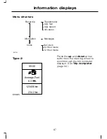
Page 87: ... and down arrow buttons to scroll through the trip computer displays to scroll through and highlight the options within a menu Press the right arrow button to enter the main menu from the trip computer displays to enter a sub menu Press the left arrow button to exit a menu Hold the left arrow button pressed at any time to return to the main menu display escape button Note The system will return to...

Page 88: ... setup X Navigation control X CD control X CD changer control X Radio control X Phone control X Auxiliary input control Type 1 E80604 Press the up and down arrow buttons on the steering wheel to scroll through the trip computer displays See Trip computer page 94 86 Information displays ...

Page 89: ...ues Messages Clock Set clock 24 Hour mode 12 Hour mode E87751 Type 2 E74426 6 3 Average Fuel 09 00 234 2 km 123456 km l 100km Press the up and down arrow buttons on the steering wheel to scroll through the trip computer displays See Trip computer page 94 87 Information displays ...

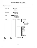
Page 90: ...h Turkish Russian Dutch Polish Portuguese Swedish Configure Language Measure unit Display Set Clock 24 Hour Mode 12 Hour Mode Always off On guidance Always on Messages Tyre Press Metric Imperial Help Screen Radio Info Phone Info NAV info Information Clock Setup B A E87752 88 Information displays ...

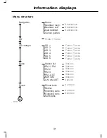
Page 91: ...ible Off Manual Auto Hill Launch Check High load Low load Tyre Pressure Full guard Ask on exit Reduced Alarm Aux Heater Parkheater B A E87753 Set Time Saturday Sunday Friday Thursday Monday Tuesday Wednesday Set Time Saturday Sunday Friday Thursday Monday Tuesday Wednesday Time 1 Time 2 Once Active now 89 Information displays ...

Page 92: ...hort period of time the display will enter a screen saver mode To access the menus from here press the left arrow button Device list The highlighted icon shows the current menu in use Navigation CD CD changer Radio Phone Trip computer Settings Auxiliary input 90 Information displays ...

Page 93: ...Folder Tracks Folder Tracks Folder Tracks Folder Tracks Folder Tracks Stations Stations Stations Stations Stations Stations Stations Numbers Numbers Numbers Station list FM 1 FM FM 2 FM 3 FM AST MW AM LW AM AST CD changer CD 1 CD 2 CD 3 CD 4 CD 5 CD 6 Radio Phone book Redial Incoming calls Outgoing calls Call status Phone A E87754 91 Information displays ...

Page 94: ...lian French Spanish Turkish Russian Dutch Polish Portuguese Swedish Colour themes Configure Language Measure unit Display Set Clock 24 hour mode 12 hour mode Always off On guidance Always on Messages Tyre Pressure Metric Imperial Help Screen NAV info Settings Information Clock Setup A C B E87755 A 92 Information displays ...

Page 95: ... Home light General warn General info Early Late Normal Forw Alert Sensitivity Warn Audible Off Manual Auto Hill Launch Check High load Low load Tyre Pressure Full guard Ask on exit Reduced Alarm Aux Heater C E87756 93 Information displays ...

Page 96: ...P COMPUTER Odometer Registers the total mileage of the vehicle Tripmeter Registers the mileage of individual journeys Distance to empty Indicates the approximate distance the vehicle will travel on the fuel remaining in the tank Changes in driving pattern may cause the value to vary Average fuel consumption Indicates the average fuel consumption since the function was last reset 94 Information dis...

Page 97: ...he steering wheel to scroll through the trip computer displays Note The position of the trip computer display may vary depending on the information shown in the display Resetting the trip computer using the main menu To reset a particular display 1 Press the right arrow button on the steering wheel to enter the main menu 2 Highlight Reset Trip with the up and down arrow buttons and press the right...

Page 98: ...ormation is displayed in the information display Type 1 and 2 1 Press the right arrow button on the steering wheel to enter the main menu 2 Highlight Setup with the up and down arrow buttons and press the right arrow button 3 Highlight Display and press the right arrow button 4 Highlight Configure and press the right arrow button 5 To toggle the Help screen Radio Info and Phone Info on and off hig...

Page 99: ...menu 2 Highlight Setup with the up and down arrow buttons and press the right arrow button 3 Highlight Display and press the right arrow button 4 Highlight Configure and press the right arrow button 5 Highlight Nav Info and press the right arrow button 6 Highlight the desired setting and press the OK button to confirm the setting 7 Press the left arrow button to exit the menu Hold the left arrow b...

Page 100: ... the desired setting and press the OK button to confirm the setting Units of measure Note The outside air temperature is only displayed in degrees Celsius and cannot be set to degrees Fahrenheit To select metric or imperial units Type 1 and 2 1 Press the right arrow button on the steering wheel to enter the main menu 2 Highlight Setup with the up and down arrow buttons and press the right arrow bu...

Page 101: ...ge has been rectified Message symbols See Owner s handbook Have the system checked at the next service Have the system checked as soon as possible Stop your vehicle as soon as it is safe to do so Viewing current messages Type 1 and 2 1 Press the right arrow button on the steering wheel to enter the main menu 2 Highlight Information with the up and down arrow buttons and press the right arrow butto...

Page 102: ... 158 amber IVDC malfunction The active suspension is set to the comfort setting IVDC comfort The active suspension is set to the normal setting IVDC normal The active suspension is set to the sport setting IVDC sport Alarm Meaning Message warning lamp Message The alarm has been triggered Check your vehicle for signs of unauthorised access amber Alarm triggered The alarm has malfunctioned Have this...

Page 103: ...ry Climate control Meaning Message warning lamp Message The auxiliary heater is on amber Aux Heater on Cruise control Adaptive cruise control ACC Meaning Message warning lamp Message Cruise control is on Cruise control active Cruise control is on standby Cruise control standby Stability control ESP may be switched off Switch ESP back on and try ACC again Otherwise try switching the ignition off an...

Page 104: ...amp Message The driver side front door is open red Driver door open The driver side rear door is open red Driver side rear door open The passenger side front door is open red Passenger door open The passenger side rear door is open red Passenger side rear door open The luggage compartment is open red Luggage comp open The bonnet is open red Bonnet open Engine immobiliser Meaning Message warning la...

Page 105: ... system Meaning Message warning lamp Message The steering system has malfunctioned Have this checked as soon as possible red Steering malfunction A valid passive key has not been recog nised amber Key not detected The engine is still running Switch the igni tion off See Keyless starting page 136 amber Car operative Press STOP A valid passive key has not been detected inside the vehicle amber Key o...

Page 106: ...bulbs have blown Check the brake lamp bulbs See Changing a bulb page 63 Stop lamps Bulb fault One or both of the brake lamp bulbs on your trailer have blown Check the brake lamp bulbs on your trailer Trailer stopl Bulb fault One or both of the direction indicator bulbs on your trailer have blown Check the direction indicator bulbs on your trailer Trailer turnl Bulb fault Maintenance Meaning Messag...

Page 107: ... Low washer fluid level The engine oil needs to be changed Have the engine oil changed as soon as possible Service oil Occupant protection Meaning Message warning lamp Message Have the system checked as soon as possible Crash mode Power steering Meaning Message warning lamp Message The power steering system has malfunc tioned Have this checked as soon as possible amber Power steering malfunction 1...

Page 108: ...ve this checked as soon as possible amber Transmission overtemperatur Tyre pressure monitoring system Meaning Message warning lamp Message The tyre indicated has continued to deflate Check the tyre and inflate it to the recom mended pressure See Technical specifications page 238 red Check tyre One or more of the tyres are significantly under inflated This message may be displayed after a new senso...

Page 109: ...ystem or a general malfunction has been detected Have the system checked as soon as possible When a malfunction occurs the system may not be able to detect or signal low tyre pres sure The tyre pressures are not suitable for driving at 160 km h 100 mph Inflate the tyres to the recommended pressure See Technical specifications page 238 This message will be displayed for only a few seconds with a lo...

Page 110: ...ng Message warning lamp Message Voice control is on Voice control Please speak Check voice control Voice control Not recognised Voice control is not allowed in this mode Voice control Not allowed 108 Information displays ...

Page 111: ...ditioning operates only when the temperature is above 4ºC 39ºF Note If you use the air conditioning the fuel consumption of your vehicle will be higher Air is directed through the evaporator where it is cooled Humidity is extracted from the air to help keep the windows free of mist The resulting condensation is directed to the outside of the vehicle and it is therefore normal if you see a small po...

Page 112: ... off the windscreen may mist up Temperature control E75471 Air distribution control E71379 A F B C D E Windscreen A Footwell and windscreen B Footwell C Face level and footwell D Face level E Face level and windscreen F You can set the air distribution control to any position between the symbols 110 Climate control ...

Page 113: ...stribution control blower and air vents to suit your requirements Air conditioning Switching the air conditioning on and off If you turn the blower off the air conditioning will turn off When you turn the blower on again the air conditioning will come on automatically Cooling with outside air E71380 Cooling the interior quickly E71381 111 Climate control ...

Page 114: ...ibution control to a position other than A the A C will remain on You can switch the air conditioning and recirculated air on and off while the air distribution control is set to position A If necessary switch the heated windows on See Heated windows and mirrors page 116 Note To defrost or demist the rear side windows set the second row air vents to the defrosting and demisting position See Air ve...

Page 115: ...s you to set different temperatures for the driver s and front passenger s side Note Avoid adjusting the settings when the vehicle interior is extremely hot or cold The automatic climate control adjusts to the current circumstances automatically For the system to function properly the side and centre vents should be fully open Note At low outside temperatures when the system is in auto mode the ai...

Page 116: ...ono mode will switch off and MONO disappears from the display The temperature for the driver s side will remain unchanged You can now adjust the driver s and passenger s side temperatures independently of each other The temperatures are shown in the display You can set a difference of up to 4ºC 7ºF Note If you set a difference of greater than 4 C 7ºF the temperature on the other side will be adjus...

Page 117: ...screen defrosting and demisting the heated screens switch on automatically and switch off after a short time To return to auto mode press the AUTO button Note To defrost or demist the rear side windows adjust the rear air vents See Air vents page 109 Switching the air conditioning on and off Press the button A C OFF or A C ON is shown in the display Recirculated air Press the button to change betw...

Page 118: ...filling stations near sources of combustible vapours or dust or in enclosed spaces The parking heater operates independently of the vehicle heater by heating the engine s coolant circuit It is fed from the vehicle fuel tank You can also use it while the vehicle is in motion to help the vehicle heater warm up the interior more quickly Used properly the parking heater provides the following benefits...

Page 119: ...ycle drive the vehicle for at least the period of the heating cycle Programming the parking heater Note The programmed time is the time at which you wish the vehicle to be warm and ready to drive not the time at which the heater switches on Note You must programme the times at least 70 minutes in advance of the time you wish to set Note You must set the time and date correctly See Clock page 130 T...

Page 120: ...tion A cross appears in the box next to the day to show that this day is selected 4 Continue in the same way to select all the days on which the heater should warm up the vehicle 5 To set the time at which the vehicle should be warmed up highlight the time at the top of the display and press the right arrow button 6 Press the OK button and the hours flash Use the up and down arrow buttons to adjus...

Page 121: ...s in warming the engine and the vehicle interior on vehicles with a diesel engine It is switched on or off automatically depending on the outside air temperature the coolant temperature and the alternator load Fuel operated heater depending on country The fuel operated heater aids in warming the engine and the vehicle interior on vehicles with a petrol or diesel engine It is switched on or off aut...

Page 122: ...child unattended in a vehicle and to never leave the keys in an unattended vehicle Note When the switches are operated often during a short period of time the system might become inoperable for a certain time to prevent damage due to overheating Note The electric sunroof can also be operated with the ignition off via the global opening and global closing function See Global opening and closing pag...

Page 123: ...ned position This position reduces the buffeting noise which is sometimes heard when the sunroof is fully open The sunroof will only stop automatically in this position when the sunroof is opened automatically To open or close the sunroof automatically press either side of the switch to the second action point and release it completely Press again to stop When the closed position is reached the su...

Page 124: ...ed automatically The sunroof will override the resistance and can then be closed fully If the sunroof does not close after the third attempt have it checked by an expert Sunroof safety mode WARNING The anti trap function is not active during this procedure Make sure that there are no obstacles in the way of the closing sunroof If the system detects a malfunction it enters a safety mode The sunroof...

Page 125: ...e the button and immediately press and hold it again The sunroof will close open fully and then close again Do not release the button before the sunroof has reached the closed position for the second time If the button is not pressed continuously the relearning function will be interrupted Start the procedure once more from the beginning 123 Climate control ...

Page 126: ...the head restraint so that the top of it is level with the top of your head and as far forwards as possible remaining comfortable keep sufficient distance between yourself and the steering wheel We recommend a minimum of 254 millimetres 10 inches between your breastbone and the airbag cover hold the steering wheel with your arms slightly bent bend your legs slightly so that you can press the pedal...

Page 127: ...easing the lever to make sure that it is fully engaged in its catch Adjusting the lumbar support E70729 Adjusting the height of the driver s seat E70730 Adjusting the angle of the seatback E70731 ELECTRIC SEATS 2 way electric seat E70733 1 1 2 2 125 Seats ...

Page 128: ...8 way electric seat 1 2 2 1 3 4 3 4 8 7 8 7 5 6 5 6 E70734 126 Seats ...

Page 129: ...e top of your head and as far forwards as possible remaining comfortable Removing the head restraint Press the locking buttons and remove the head restraint REAR SEATS WARNINGS When folding the seatbacks down take care not to get your fingers caught between the seatback and seat frame Make sure that the seats and the seatbacks are secure and fully engaged in their catches Folding the seatbacks dow...

Page 130: ...estraints 2 1 3 2 E86612 1 Insert your fingers between the seat cushion and seatback and fold the seat cushion forwards 2 Press the unlock buttons down and hold them there 3 Push the seatback forwards HEATED SEATS CAUTION Operating this function with the engine off will drain the battery E70601 E71224 Note The settings are stored when you switch off the ignition 128 Seats ...

Page 131: ... being ventilated the heater may switch on automatically This is to prevent the flow of air becoming uncomfortably cool Note The air in the vehicle interior is used to ventilate the seats The cooling effect therefore depends on the temperature of the vehicle interior Switch on the air conditioning if necessary and set the air distribution to footwell See Climate control page 109 129 Seats ...

Page 132: ...y set the date and time on the clock using GPS signals Note See General information page 85 1 From the main menu select the clock function 2 Select the option required 3 Press OK 4 Using the right left up and down arrow buttons select and change the value 5 Press OK CIGAR LIGHTER CAUTIONS If you use the socket when the engine is not running the battery may discharge 130 Convenience features ...

Page 133: ... 15 Amperes Use only Ford accessory connectors or connectors specified for use with SAE standard sockets E72972 Press the element in to use the cigar lighter It will pop out automatically ASHTRAY Front ashtray E72974 To empty pull out the complete ashtray Rear ashtray E73705 To remove the ashtray open it press it down against the spring and remove it AUXILIARY POWER SOCKETS CAUTION If you use the ...

Page 134: ... sockets E86470 CUP HOLDERS WARNING Do not place hot drinks in the cup holders when the vehicle is moving GLOVE BOX Cooled glove box Note You can cool the glove box using air from the air conditioning system E70885 STORAGE COMPARTMENTS WARNING Do not drive with any storage compartment lid open Make sure that you secure the lid before setting off CAUTION Do not keep heat sensitive items and liquids...

Page 135: ... WARNINGS Before activating the seat memory make sure that the area immediately surrounding the seat is clear of obstructions and that all occupants are clear of moving parts Do not use the memory store function when the vehicle is moving 133 Convenience features ...

Page 136: ...er Each time you turn the ignition off the current seat and mirror settings are stored on the remote control or passive key used Active setting 1 Turn the ignition on 2 Adjust the seat and exterior mirrors to the desired position 3 Press and hold the desired pre set button B until a single chime sounds to confirm Easy entry easy exit To allow the driver to enter and exit the vehicle with ease the ...

Page 137: ...aler Note If more than one passive keys are in range the memory function will move to the settings of the first key stored When you unlock the vehicle with the remote control or pull the driver door handle with a passive key in range the seat and mirrors will move to the position stored on that remote control or passive key Active recall Press the pre set button associated with the desired driving...

Page 138: ...cuits are disabled Note Do not leave the ignition key in this position for too long to avoid discharging the battery II The ignition is switched on All electrical circuits are operational Warning lamps and indicators illuminate This is the key position when driving You must also select it when being towed III The starter motor is activated Release the key as soon as the engine starts KEYLESS START...

Page 139: ...s soon as the engine starts Note Releasing the start button or the clutch pedal during engine start will stop the engine cranking and return to ignition on 1 Fully depress the clutch pedal 2 Press the start button Starting a diesel engine Note Engine cranking will not commence until the engine glow plug cycle has been completed This may take several seconds in extremely cold conditions Note Contin...

Page 140: ...tion you can use the start button to switch the ignition on and start your vehicle Stopping the engine When your vehicle is stationary press the start button to stop the engine The ignition all electrical circuits warning lamps and indicators will be switched off STEERING WHEEL LOCK WARNING Always check that the steering is unlocked before attempting to move your vehicle Vehicles without keyless s...

Page 141: ...nsmission Note Do not touch the accelerator pedal 1 Fully depress the clutch pedal 2 Start the engine Vehicles with automatic transmission Note Do not touch the accelerator pedal 1 Select park or neutral 2 Fully depress the brake pedal 3 Start the engine All vehicles If the engine does not start within 15 seconds wait for a short period and try again If the engine does not start after three attemp...

Page 142: ...ntinue cranking the engine until it starts Note You can only operate the starter for a maximum of 30 seconds at a time Switch the ignition on and wait until the glow plug indicator goes off Vehicles with manual transmission Note Do not touch the accelerator pedal 1 Fully depress the clutch pedal 2 Start the engine Vehicles with automatic transmission 1 Select park or neutral 2 Fully depress the br...

Page 143: ...very 500 800 kilometres 300 500 miles To do this drive your vehicle at 80 km h 50 mph for 40 kilometres 25 miles in the lowest possible gear whenever it is safe to do so Alternatively drive normally but use a lower gear SWITCHING OFF THE ENGINE Vehicles with a turbocharger CAUTION Do not switch the engine off when it is running at high speed If you do the turbocharger will continue running after t...

Page 144: ...tion defined by EN 228 or equivalent FUEL QUALITY DIESEL Note We recommend that you use only high quality fuel without additives or other engine treatments WARNING Do not mix diesel with oil petrol or other liquids This could cause a chemical reaction CAUTION Do not add kerosene paraffin or petrol to diesel This could cause damage to the fuel system Note We do not recommend the prolonged use of ad...

Page 145: ...uel to drain into the fuel tank CAUTION If you use a high pressure spray to wash your vehicle only spray the fuel filler flap briefly from a distance not less than 20 centimetres 8 inches E86613 Press the flap to open it Open the flap fully until it engages When you insert the fuel pipe nozzle a spring loaded inhibitor will open if the correct size nozzle is detected This will prevent filling up w...

Page 146: ...not intended to represent the real world fuel consumption you may get from your vehicle Real world fuel consumption is governed by many factors including driving style high speed driving stop start driving air conditioning usage the accessories fitted and towing etc Your Ford dealer can give you advice on improving your fuel consumption TECHNICAL SPECIFICATIONS 4 door and 5 door Fuel consumption f...

Page 147: ...125 PS 156 5 9 47 9 4 9 57 6 7 6 37 2 2 0L Duratorq TDCi 6 speed manual transmis sion 189 7 1 39 8 5 6 50 4 9 8 28 8 2 0L Duratorq TDCi 130 PS 6 speed automatic transmission Information not avail able Information not avail able Information not avail able Information not avail able 2 2L Duratorq TDCi 6 speed manual transmis sion Information not avail able Information not avail able Information not ...

Page 148: ... 222 9 3 30 4 6 8 41 5 13 6 20 8 2 5L Duratec ST 220 PS 154 5 8 48 7 4 8 58 9 7 5 37 7 1 8L Duratorq TDCi 156 5 9 47 9 4 9 57 6 7 6 37 2 2 0L Duratorq TDCi 189 7 1 39 8 5 6 50 4 9 8 28 8 2 0L Duratorq TDCi 130 PS 6 speed automatic transmission Information not avail able Information not avail able Information not avail able Information not avail able 2 2L Duratorq TDCi 6 speed manual transmis sion ...

Page 149: ... to the inadvertent selection of 2nd gear and can cause damage to the transmission Note Fully depress the clutch pedal and wait for three seconds before you select first gear Vehicles with a 5 speed transmission Selecting reverse gear E75050 Vehicles with a 6 speed transmission 2 5L Duratec ST engine Selecting reverse gear E75051 1 2 Vehicles with a 6 speed transmission Turbo diesel engines Select...

Page 150: ...icle is stationary Apply the parking brake and select park before leaving your vehicle Make sure that the selector lever is latched in position Note An audible warning will sound if you open the driver s door and you have not selected park In this position power is not transmitted to the drive wheels and the transmission is locked You can start the engine with the selector lever in this position R...

Page 151: ...ssion will select the appropriate gear for optimum performance based on ambient temperature road gradient vehicle load and driver input Hints on driving with an automatic transmission Moving off 1 Release the parking brake 2 Release the brake pedal and press the accelerator pedal Stopping 1 Release the accelerator pedal and press the brake pedal 2 Apply the parking brake Kickdown Press the acceler...

Page 152: ...E87934 1 Remove the centre console side panel E87935 Note The lever is yellow 1 Insert a flat bladed screwdriver into the slot and turn the screwdriver clockwise 90 degrees 150 Transmission ...

Page 153: ...educed braking efficiency Dab the brake pedal when driving from a car wash to remove the film of water ABS WARNING The ABS does not relieve you of your responsibility to drive with due care and attention The ABS helps you to maintain full steering and directional stability when you brake heavily in an emergency by preventing the road wheels from locking The ABS monitors the speed of each road whee...

Page 154: ... the release button when you apply the parking brake 1 Press the brake pedal firmly 2 Pull the parking brake lever upwards to its fullest extent Parking on a hill If you have to park facing uphill select first gear and turn the front wheels away from the kerb If you have to park facing downhill select reverse gear and turn the front wheels towards the kerb Releasing the parking brake 1 Press the b...

Page 155: ...ves your ability to pull away on slippery roads or loose surfaces and improves comfort by limiting wheel spin in hairpin bends Stability control ESP warning lamp The ESP warning lamp will flash when the system is operating See Warning lamps and indicators page 81 Emergency brake assist WARNING Emergency brake assist does not relieve you of your responsibility to drive with due care and attention E...

Page 156: ... switch will illuminate A message will be shown in the display See Information messages page 99 Press the switch again to turn the system on The system will be switched on automatically every time you switch the ignition on 154 Stability control ...

Page 157: ...G The HLA does not replace the parking brake When you leave the vehicle always apply the parking brake and select first or reverse gear USING HLA The HLA can operate in either automatic or manual mode If you select automatic mode the HLA is activated automatically when the vehicle is on a slope and you press the brake pedal If you select manual mode you must activate the HLA using the brake pedal ...

Page 158: ...engaged On vehicles with manual transmission the clutch pedal is pressed On vehicles with automatic transmission the driver door is closed No failure mode is present To activate the HLA in automatic mode 1 Press the brake pedal to bring the vehicle to a complete standstill Keep the brake pedal depressed 2 If the sensors detect that the vehicle is on a slope and the right driving direction is selec...

Page 159: ...be repaired during the next service The message Hill Launch A not available will also be displayed with manual activation during a failure or if one of the activation criteria is not met If you have switched the HLA off no messages will be displayed Deactivating the HLA To deactivate the HLA perform one of the following Apply the parking brake Wait for two to three seconds until the HLA deactivate...

Page 160: ...e will react stronger to the road and driving conditions compared to the comfort setting The dynamic behaviour of the vehicle in this setting is similar to the typical Ford passenger car performance Sport In this setting the dampers are more sporty and maximum body control is provided The body will follow the road to reduce roll during hard cornering giving you the feeling of a typical sports car ...

Page 161: ...er sensors will detect rearward objects USING THE PARKING AID Note Keep the sensors free from dirt ice and snow Do not clean with sharp objects Switching the parking aid on and off Note The parking aid switches off automatically when you start the engine or when you exceed 16 km h 10 mph Note Vehicles fitted with a trailer tow module not approved by us may not correctly detect obstacles Note On ve...

Page 162: ...e light in the switch is flashing it indicates a malfunction The system will be disabled Have the system checked by properly trained technicians You will hear an intermittent tone at a distance of up to 180 centimetres 71 inches between the obstacle and rear bumper 80 centimetres 31 inches between the obstacle and front bumper and 60 centimetres 24 inches to the side Decreasing the distance accele...

Page 163: ...switch to store and maintain your current speed The cruise control indicator illuminates Changing the set speed WARNING When you are going downhill your speed may increase above the set speed The system will not apply the brakes Change down a gear and press the RES switch to assist the system in maintaining the set speed Note If you accelerate by pressing the accelerator pedal the set speed will n...

Page 164: ...etain the speed that you previously set Resuming the set speed E70616 Press the RES switch The cruise control indicator illuminates and the system will attempt to resume the speed that you previously set Switching cruise control off E70613 Press the OFF switch The system will not retain the speed that you previously set The cruise control indicator will go off 162 Cruise control ...

Page 165: ...tervene when adaptive cruise control is not maintaining a suitable speed or suitable distance The adaptive cruise control does not brake for slow or stationary vehicles WARNINGS When ACC is activated you may hear some unusual sounds during automatic braking This is normal and caused by the automatic braking system The adaptive cruise control system is based on the use of a radar sensor which proje...

Page 166: ...y be detected late or not at all There may be issues with the detection of vehicles in front when going into and coming out of a bend C The detection beam will not follow sharp curves in the road WARNING In these cases ACC may brake late or unexpectedly The driver should stay alert and intervene if necessary Automatic braking with ACC Adaptive cruise control will automatically brake for you if req...

Page 167: ...orarily deactivated and then reactivated when the accelerator pedal is released ACC override is displayed in the information display A C E D B E82310 ACC on off A ACC cancel B Forward alert on off C ACC gap increase D ACC gap decrease E Switching ACC on Press switch A The system is set to standby mode and Standby is displayed in the information display Setting a speed E70615 Note The system must b...

Page 168: ... the information display below the bars The system will maintain the set speed when conditions permit The set gap is maintained and displayed If a vehicle is detected by the sensor the display will show another vehicle above the horizontal bars E82312 This is a follow mode and the system will accelerate or decelerate as necessary to maintain the set gap Press switch E to decrease the gap or switch...

Page 169: ...alfunctioning or reacting to an emergency the system is automatically deactivated In the event of automatic deactivation a signal will sound and the message ACC cancel is displayed in the information display You must then intervene and adapt your driving and speed to vehicles in front An automatic deactivation can be due to the vehicle speed falling below 30 km h 20 mph wheels lose traction brake ...

Page 170: ...gencies only The system alerts you by warning chimes and a visual warning in the information display When forward alert is activated a red flashing warning triangle is displayed in the information display Note You can deactivate the warning chimes by using the buttons on the steering wheel See Audible warnings and indicators page 84 The system does not operate in all driving situations and traffic...

Page 171: ...rt on off E94165 The indicator will illuminate Adjusting the warning sensitivity You may adjust the system warning sensitivity using the buttons on the steering wheel See General information page 85 This controls how early the visual and audible warning is activated 169 Adaptive cruise control ACC ...

Page 172: ...or your vehicle See Vehicle identification page 242 LUGGAGE ANCHOR POINTS Estate E86912 4 door and 5 door E86913 SLIDING LOADSPACE FLOOR WARNING Do not slide the loadspace floor rearwards when the vehicle is standing on an incline of 15 degrees or more and facing uphill CAUTION The maximum permissible weight on the sliding loadspace floor is 200 kilogrammes 441 pounds The maximum permissible weigh...

Page 173: ...n To slide it forwards press the unlocking handle and push it forwards Note You do not have to exert as much pressure on the unlocking handle if you push the loadspace floor forwards slightly when operating it Storage compartment A storage compartment is located in the floor at the rear of the luggage compartment To gain access to the storage compartment lift up the sliding loadspace floor as foll...

Page 174: ...using the loop To return the loadspace floor to the normal position 1 Hold the floor with one hand and release the support leg with the other hand 2 Insert the support leg back into the clip 3 Lower the floor 4 Press the unlocking handle and pull the loadspace floor rearwards until it drops into position on the rails REAR UNDER FLOOR STORAGE Vehicles with a sliding loadspace floor Raise the loadsp...

Page 175: ...e retainers on the roof Push the bar forwards into the narrow section of the retainers E87053 2 Attach the net to the luggage anchor points See Luggage anchor points page 170 E87054 3 Tighten the belts Removing the net E87135 1 Release the belts 2 Remove the net from the luggage anchor points 3 Remove the upper bars 173 Load carrying ...

Page 176: ...fuel consumption of your vehicle will be higher and you may experience different driving characteristics Read and follow the manufacturer s instructions when you are fitting a roof rack CAUTION Do not exceed the maximum permissible roof load of 75 kilogrammes 165 pounds including the roof rack Check the security of the roof rack and tighten its fittings as follows before starting after driving 50 ...

Page 177: ...retainers on the roof Push the bar forwards into the narrow section of the retainers E87782 2 Attach the dog guard to the lower anchor points Do not tighten the screws E87783 3 Attach the grille to the lower bar with the handwheels Do not tighten the handwheels 4 Tighten the screws at the lower anchor points 5 Tighten the handwheels 175 Load carrying ...

Page 178: ...nts See Luggage anchor points page 170 E86842 3 Tighten the handwheels Remove in the reverse order LOAD RETAINING FIXTURES WARNING Do not exceed the maximum permissible load of 60 kilogrammes 132 pounds on two load retaining fixtures and 30 kilogrammes 66 pounds on one Check the security of the load retaining fixtures and tighten its fittings as follows before starting after driving 50 kilometres ...

Page 179: ...cle If you install it the wrong way round it may not hold the box in place in the event of an accident Do not exceed the maximum permissible load of 20 kilogrammes 44 pounds 1 2 3 3 E76378 1 Turn the box over 2 Position the load bracket 3 Secure the load bracket with four screws E76379 4 Slide the captured bolts onto the load retaining fixture 177 Load carrying ...

Page 180: ...E76380 5 Secure the load bracket with the two wing nuts 6 Remove in the reverse order 178 Load carrying ...

Page 181: ...quality of the trailer In high altitude regions the stipulated maximum permitted gross train weight must be reduced by 10 for every 1 000 metres 3 281 feet Steep gradients WARNING The overrun brake on a trailer is not controlled by ABS Change down a gear before you reach a steep downhill gradient DETACHABLE TOW BALL WARNINGS When not in use always transport the tow ball arm securely fastened in th...

Page 182: ...wheel must align with the green mark on the tow ball 4 Release the handwheel The tow ball arm is unlocked Inserting the tow ball arm 1 2 E71330 WARNING The tow ball arm may only be inserted when completely unlocked 1 Pull out the plug 2 Insert the tow ball arm vertically and press it upwards until it engages 1 Do not hold your hand near the handwheel 3 The green mark on the handwheel must align wi...

Page 183: ...y locked Check the green marks are aligned the handwheel A is correctly fitted to the tow ball arm you have removed the key B the tow ball arm is securely positioned It must not move when jerked Removing the tow ball arm 3 1 E71332 2 1 Unhitch the trailer 2 Remove the protecting cap Press the cap into the key bow Insert the key and unlock 1 3 Hold the tow ball arm Pull the handwheel out turn it cl...

Page 184: ...emove the tow ball arm and protect the seat with the plug before steam cleaning your vehicle Keep the system clean Periodically lubricate bearings sliding surfaces and locking balls with resin free grease or oil and the lock with graphite Keep a note of the key number In case of loss replacement keys are available from the manufacturer by stating the 4 digit key number 182 Towing ...

Page 185: ...s and clutch WARNING Avoid heavy use of the brakes and clutch if possible for the first 150 kilometres 100 miles in town and for the first 1 500 kilometres 1 000 miles on motorways Engine CAUTION Avoid driving too fast during the first 1 500 kilometres 1 000 miles Vary your speed frequently and change up through the gears early Do not labour the engine 183 Driving hints ...

Page 186: ...FIRST AID KIT 4 door E87654 5 door E87655 Estate E87656 WARNING TRIANGLE 4 door E87657 184 Emergency equipment ...

Page 187: ...5 door E87658 Estate with medium size spare wheel E87771 Estate with full size spare wheel E87772 Vehicles with tyre repair kit E87659 See Rear under floor storage page 172 185 Emergency equipment ...

Page 188: ...SPECTING SAFETY SYSTEM COMPONENTS Seat belts Belts subjected to strain as a result of an accident should be renewed and the anchorages checked by a properly trained technician 186 Status after a collision ...

Page 189: ...oosen the screws E72590 2 Turn the knob through 90 degrees and release the fuse box from the retaining bracket 3 Lower the fuse box and pull it towards you E72622 4 Remove the cover to gain access to the fuses vehicles with a cooled glove box 5 Install in the reverse order 187 Fuses ...

Page 190: ...or and 5 door 1 E87481 1 Remove the cover 2 E87482 2 Remove the relevant fuse box cover Rear fuse box Estate 1 2 E87479 1 Release the catches 2 Remove the cover 3 3 3 E87480 3 Remove the relevant fuse box cover 188 Fuses ...

Page 191: ...roperly trained technician Switch the ignition and all electrical equipment off before touching or attempting to change a fuse CAUTION Fit a replacement fuse with the same rating as the one you have removed Note You can identify a blown fuse by a break in the filament Note All fuses except high current fuses are a push fit Note A fuse puller is located in the engine compartment fuse box 189 Fuses ...

Page 192: ...FUSE SPECIFICATION CHART Engine compartment fuse box E75525 Circuits protected Colour Ampere rating Fuse Transmission control module red 10 F1 Glow plug monitoring diesel engines tan 5 F2 190 Fuses ...

Page 193: ... control module red 10 F8 Not used F9 Engine control module red 10 F10 Valves MAF control engine manage ment red 10 F11 Water in fuel sensor coils MAF engine management diesel engine red 10 F12 Air conditioning relay blue 15 F13 Diesel filter heater blue 15 F14 Starter relay orange 40 F15 Diesel auxiliary heater PTC clear 80 F16 Central fuse box supply A blue 60 F17 Central fuse box supply B blue ...

Page 194: ...lue 15 F31 Not used F32 Light switch module engine compart ment fuse box coils tan 5 F33 Heated windscreen left hand side orange 40 F34 Heated windscreen right hand side orange 40 F35 ABS tan 5 F36 Heated front washer jets red 10 F37 Adaptive cruise control ACC tan 5 F38 Adaptive front lighting system AFS blue 15 F39 Not used F40 Instrument panel yellow 20 F41 Engine control module transmission co...

Page 195: ...use Headlamp levelling adaptive front lighting system AFS tan 5 F43 Vacuum pump 2 5L Duratec HE yellow 20 F44 Rear window wiper blue 15 F45 1 Fit a replacement with the same rating as the one you have removed Central fuse box E75527 193 Fuses ...

Page 196: ...ntrol blue 15 F6 Steering wheel module brown 7 5 F7 Instrument cluster tan 5 F8 Main beam blue 15 F9 Power sunroof yellow 20 F10 Reversing lamps brown 7 5 F11 Not used F12 Front fog lamp blue 15 F13 Windscreen washers blue 15 F14 Adaptive cruise control ACC red 10 F15 Not used F16 Interior lamps red 10 F17 Engine immobiliser tan 5 F18 Cigar lighter blue 15 F19 Not used F20 Audio unit rain sensor t...

Page 197: ...ating Fuse Ignition switch tan 5 F24 Fuel filler flap red 10 F25 Battery backup sounder alarm system OBD II board computer diagnostics tan 5 F26 Steering column unit climate control module tan 5 F27 Brake lamp switch tan 5 F28 195 Fuses ...

Page 198: ...Rear fuse box 4 door and 5 door E87483 196 Fuses ...

Page 199: ...Estate E75526 Circuits protected Colour Ampere rating Fuse Door module left hand front window up down central locking electric folding mirror heated mirror clear 25 FA1 197 Fuses ...

Page 200: ...uxiliary power socket blue 15 FA6 Relay coils tan 5 FA7 Steering column lock yellow 20 FA8 Not used FA9 Electric driver s seat green 30 FA10 Accessories trailer module yellow 20 FA11 Not used FA12 Parking aid module tan 5 FB1 Suspension module blue 15 FB2 Heated driver s seat blue 15 FB3 Heated front passenger seat blue 15 FB4 Left hand rear heated seat blue 15 FB5 Not used FB6 Right hand rear hea...

Page 201: ...t used FB12 Not used FC1 Not used FC2 Not used FC3 Not used FC4 CD changer rear seat entertainment system brown 7 5 FC5 Not used FC6 Seat memory function module tan 5 FC7 Keyless entry yellow 20 FC8 Not used FC9 Not used FC10 Not used FC11 Not used FC12 199 Fuses ...

Page 202: ...hout tyre repair kit E87283 Vehicles with tyre repair kit E87281 The screw in towing eye is located in the spare wheel well The towing eye must always be carried in the vehicle Insert your finger into the hole on the underside of the cover and prise off the cover Install the towing eye CAUTION The screw in towing eye has a left hand thread Turn it anti clockwise to install it 200 Vehicle recovery ...

Page 203: ...our vehicle or the vehicle that is towing Do not use a rigid tow bar on the front towing eye Drive off slowly and smoothly without jerking the vehicle that is towing Vehicles with automatic transmission CAUTIONS Do not tow your vehicle faster than 50 km h 30 mph or further than 50 kilometres 30 miles CAUTIONS If a speed of 50 km h 30 mph and a distance of 50 kilometres 30 miles is to be exceeded t...

Page 204: ...e ignition on or when the engine is running The system operates at high voltage Keep your hands and clothing clear of the engine cooling fan Under certain conditions the fan may continue to run for several minutes after you have switched the engine off Daily checks Exterior lamps Interior lamps Warning lamps and indicators Check when refuelling Engine oil level See Engine oil check page 213 Brake ...

Page 205: ... the catch towards the left hand side of the vehicle E87786 Open the bonnet and support it with the strut Closing the bonnet WARNING Make sure that the bonnet is closed properly Lower the bonnet and allow it to drop from under its own weight for the last 20 30 centimetres 8 11 inches 203 Maintenance ...

Page 206: ...ler cap 1 See Engine oil check page 213 B Brake and clutch fluid reservoir left hand drive See Brake and clutch fluid check page 215 C Battery See Vehicle battery page 222 D Engine compartment fuse box See Fuses page 187 E Air cleaner No maintenance necessary F Screen washer fluid reservoir See Washer fluid check page 216 G Engine oil dipstick 1 See Engine oil check page 213 H 204 Maintenance ...

Page 207: ...MPARTMENT OVERVIEW 2 0L DURATEC HE MI4 A C G J F D E B H I E73231 Brake and clutch fluid reservoir right hand drive See Brake and clutch fluid check page 215 A Engine oil filler cap 1 See Engine oil check page 213 B Brake and clutch fluid reservoir left hand drive See Brake and clutch fluid check page 215 C Battery See Battery care page 222 D Engine compartment fuse box See Fuse specification char...

Page 208: ... fluid check page 215 I Engine coolant reservoir See Engine coolant check page 214 J 1 The filler caps and the engine oil dipstick are coloured for easy identification ENGINE COMPARTMENT OVERVIEW 2 3L DURATEC HE MI4 E81313 A C G J F D E B H I Brake and clutch fluid reservoir right hand drive See Brake and clutch fluid check page 215 A Engine oil filler cap 1 See Engine oil check page 213 B 206 Mai...

Page 209: ...ary F Screen washer fluid reservoir See Washer fluid check page 216 G Engine oil dipstick 1 See Engine oil check page 213 H Power steering fluid reservoir See Power steering fluid check page 215 I Engine coolant reservoir See Engine coolant check page 214 J 1 The filler caps and the engine oil dipstick are coloured for easy identification ENGINE COMPARTMENT OVERVIEW 2 5L DURATEC ST VI5 A C G J I F...

Page 210: ... page 222 D Engine compartment fuse box See Fuse specification chart page 190 E Screen washer fluid reservoir See Washer fluid check page 216 F Air cleaner No maintenance necessary G Engine oil dipstick 1 See Brake and clutch fluid check page 215 H Power steering fluid reservoir See Power steering fluid check page 215 I Engine coolant reservoir See Engine coolant check page 214 J 1 The filler caps...

Page 211: ...1 See Engine oil check page 213 B Brake and clutch fluid reservoir left hand drive See Brake and clutch fluid check page 215 C Battery See Battery care page 222 D Engine compartment fuse box See Fuse specification chart page 190 E Air cleaner No maintenance necessary F Screen washer fluid reservoir See Washer fluid check page 216 G Engine oil dipstick 1 See Engine oil check page 213 H 209 Maintena...

Page 212: ...MENT OVERVIEW 2 0L DURATORQ TDCI DW DIESEL A C G J I F D E B H E73234 Brake and clutch fluid reservoir right hand drive See Brake and clutch fluid check page 215 A Engine oil filler cap 1 See Engine oil check page 213 B Brake and clutch fluid reservoir left hand drive See Brake and clutch fluid check page 215 C Battery See Battery care page 222 D Engine compartment fuse box See Fuse specification ...

Page 213: ...d check page 215 I Engine coolant reservoir See Engine coolant check page 214 J 1 The filler caps and the engine oil dipstick are coloured for easy identification ENGINE COMPARTMENT OVERVIEW 2 2L DURATORQ TDCI DW DIESEL A C G J F D E B H I E87715 Brake and clutch fluid reservoir right hand drive See Brake and clutch fluid check page 215 A Engine oil filler cap 1 See Engine oil check page 213 B 211...

Page 214: ...luid check page 216 G Engine oil dipstick 1 See Engine oil check page 213 H Power steering fluid reservoir See Power steering fluid check page 215 I Engine coolant reservoir See Engine coolant check page 214 J 1 The filler caps and the engine oil dipstick are coloured for easy identification ENGINE OIL DIPSTICK 1 6L DURATEC 16V TI VCT SIGMA E95540 B A MIN A MAX B ENGINE OIL DIPSTICK 2 0L DURATEC H...

Page 215: ...TORQ TDCI DW DIESEL E95543 B A MIN A MAX B ENGINE OIL CHECK CAUTION Do not use oil additives or other engine treatments Under certain conditions they could damage the engine Note The oil consumption of new engines reaches its normal level after approximately 5 000 kilometres 3 000 miles Checking the oil level CAUTION Make sure that the level is between the MIN and the MAX marks 213 Maintenance ...

Page 216: ...d that meets the Ford specification See Technical specifications page 216 ENGINE COOLANT CHECK Checking the coolant level WARNING Do not allow the fluid to touch your skin or eyes If this happens rinse the affected areas immediately with plenty of water and contact your doctor CAUTION Make sure that the level is between the MIN and the MAX marks Note Coolant expands when it is hot The level may th...

Page 217: ...ir If the level is at the MIN mark top up immediately Topping up Remove the filler cap CAUTION Do not top up further than the MAX mark Top up with fluid that meets the Ford specification See Technical specifications page 216 POWER STEERING FLUID CHECK WARNING Do not allow the fluid to touch your skin or eyes If this happens rinse the affected areas immediately with plenty of water and contact your...

Page 218: ...quirements Use of unsuitable oil may lead to engine damage which is not covered by your Warranty You can use an alternative SAE 5W 30 engine oil providing it meets the specification defined by WSS M2C913 B Note If you operate your vehicle in temperatures below 20 C 4 F you must not use SAE 10W 40 engine oil Topping up the oil If you are unable to find an oil that meets the specification defined by...

Page 219: ...6L Duratec 16V Ti VCT 70 15 4 Fuel tank 1 6L Duratec 16V Ti VCT 4 3 1 0 Engine lubrication system including the oil filter 2 0L Duratec HE 3 9 0 9 Engine lubrication system excluding the oil filter 2 0L Duratec HE 6 2 1 4 Engine cooling system 2 0L Duratec HE 70 15 4 Fuel tank 2 0L Duratec HE 4 3 1 0 Engine lubrication system including the oil filter 2 3L Duratec HE 3 9 0 9 Engine lubrication syst...

Page 220: ... lubrication system excluding the oil filter 1 8L Duratorq TDCi 7 9 1 7 Engine cooling system 1 8L Duratorq TDCi 70 15 4 Fuel tank 1 8L Duratorq TDCi 5 5 1 2 Engine lubrication system including the oil filter 2 0L Duratorq TDCi 5 0 1 1 Engine lubrication system excluding the oil filter 2 0L Duratorq TDCi 8 1 1 8 Engine cooling system 2 0L Duratorq TDCi 70 15 4 Fuel tank 2 0L Duratorq TDCi 6 0 1 3 ...

Page 221: ...Capacity in litres gallons Item Variant 8 4 1 9 Engine cooling system 2 2L Duratorq TDCi 70 15 4 Fuel tank 2 2L Duratorq TDCi 219 Maintenance ...

Page 222: ...cal solvents to clean them Do not wipe the headlamps when they are dry Cleaning the rear window CAUTION Do not scrape the inside of the rear window or use abrasives or chemical solvents to clean it Use a clean lint free cloth or a damp chamois leather to clean the inside of the rear window Cleaning the chrome trim CAUTION Do not use abrasives or chemical solvents Use soapy water Body paintwork pre...

Page 223: ...ry naturally away from artificial heat REPAIRING MINOR PAINT DAMAGE CAUTION Remove apparently harmless looking substances from the paintwork immediately e g bird droppings tree resins insect remains tar spots road salt and industrial fall out You should repair paintwork damage caused by stones from the road or minor scratches as soon as possible A choice of products is available from your Ford Dea...

Page 224: ...USING BOOSTER CABLES CAUTIONS Connect batteries with only the same nominal voltage Always use booster cables with insulated clamps and adequate size cable Do not disconnect the battery from the vehicle s electrical system To connect the booster cables A B C D E75183 Flat battery vehicle A Booster battery vehicle B 222 Vehicle battery ...

Page 225: ...left hand side suspension turret of vehicle A cable D CAUTIONS Do not connect to the negative terminal of the flat battery Make sure that the jump leads are clear of any moving parts To start the engine 1 Run the engine of vehicle B at moderately high speed 2 Start the engine of vehicle A 3 Run both vehicles for a minimum of three minutes before disconnecting the cables CAUTION Do not switch on th...

Page 226: ...in a replacement locking wheel nut key and replacement locking wheel nuts from your dealer using the reference number certificate Vehicle jack WARNINGS The vehicle jack supplied with your vehicle should only be used when changing a wheel in emergency situations Before using the vehicle jack check that it is not damaged or deformed and that the thread is lubricated and free from foreign matter Neve...

Page 227: ...g wheel nut key C Your vehicle jack and wheel brace are located in the spare wheel well Jacking and lifting points CAUTION Use only the specified jacking points If you use other positions you may damage the body steering suspension engine braking system or the fuel lines E92658 A B 225 Wheels and tyres ...

Page 228: ... E92932 E93020 Vehicles with side skirts E95345 Removing a road wheel WARNINGS Park your vehicle in such a position that neither the traffic nor you are hindered or endangered Set up a warning triangle Make sure that the vehicle is on firm level ground with the wheels pointing straight ahead 226 Wheels and tyres ...

Page 229: ...t is supported only by a jack Make sure that the jack is vertical to the jacking point and the base is flat on the ground CAUTION Do not lay alloy wheels face down on the ground this will damage the paint Note The spare wheel is located under the floor cover in the luggage compartment 1 Insert the flat end of the wheel brace between the rim and the hub cover and carefully remove the hub cap or cov...

Page 230: ...stall the wheel 2 Install the wheel nuts finger tight E71948 3 Install the locking wheel nut key 1 2 3 4 5 E75442 4 Partially tighten the wheel nuts in the sequence shown 5 Lower the vehicle and remove the jack 6 Fully tighten the wheel nuts in the sequence shown See Technical specifications page 238 7 Install the hub cap or cover using the ball of your hand WARNING Have the wheel nuts checked for...

Page 231: ...er of up to six millimetres 1 4 inch to temporarily restore mobility Observe the following rules when using the kit Drive with caution and avoid making sudden steering or driving manoeuvres especially if the vehicle is heavily loaded or you are towing a trailer The kit will provide you with an emergency temporary repair enabling you to continue your journey to the next vehicle or tyre dealer or to...

Page 232: ...e observed Inflating the tyre WARNINGS Check the sidewall of the tyre prior to inflation If there are any cracks bumps or similar damage do not attempt to inflate the tyre WARNINGS Do not stand directly beside the tyre while the compressor is pumping Watch the sidewall of the tyre If any cracks bumps or similar damage appear turn off the compressor and let the air out by means of the pressure reli...

Page 233: ...E94973 B J I F E C K A G H D Protective cap A Pressure relief valve B Hose C Orange cap D 231 Wheels and tyres ...

Page 234: ...he compressor switch H is in position 0 9 Insert the power plug G into the cigar lighter socket or auxiliary power socket See Cigar lighter page 130 See Auxiliary power sockets page 131 10 Start the engine 11 Move the compressor switch H to position 1 12 Inflate the tyre for no longer than seven minutes to an inflation pressure of minimum 1 8 bar 26 psi and a maximum of 3 5 bar 51 psi Move the com...

Page 235: ...nflation procedure once again to top up the tyre 5 Check the tyre pressure again from the pressure gauge F If the tyre pressure is too high deflate the tyre to the specified pressure using the pressure relief valve B 6 Once you have inflated the tyre to its correct tyre pressure move the compressor switch H to position 0 remove the power plug G from the socket unscrew the hose C fasten the valve c...

Page 236: ...pressure B Tyre C Reinforced sidewall D When a standard tyre experiences a drastic loss of inflation pressure the rim of the wheel brings the full weight of the vehicle to bear on the collapsed sidewalls You can barely manoeuvre the vehicle and the tyre is destroyed Run flat tyres have sturdy reinforced sidewalls that support the rim should the tyre suffer a loss of inflation pressure What to do i...

Page 237: ...es It must be pointed out to the driver that the standard tyre has no runflat properties Do not fit run flat tyres on vehicles that were not originally fitted with them Please contact your dealer for more details regarding compatibility Run flat tyres may be sold and mounted only by specially trained and certified tyre dealers TYRE CARE E70415 To make sure the front and rear tyres of your vehicle ...

Page 238: ...relieve you of your responsibility to regularly check the tyre pressures The system will only provide a low tyre pressure warning It will not inflate the tyres The system may take longer to detect low pressure in the tyres if you have fitted snow chains Do not drive on significantly under inflated tyres This may cause the tyres to overheat and fail Under inflation reduces fuel efficiency tyre trea...

Page 239: ... the steering wheel to enter the main menu 2 Highlight Information with the up and down buttons and press the right arrow button 3 Highlight Tyre Pressures with the up and down buttons and press the right arrow button 4 Highlight the desired setting and press the OK button to confirm the setting 5 Press the left arrow button to exit the menu Hold the left arrow button pressed to return to the trip...

Page 240: ... to exit the menu Hold the left arrow button pressed to return to the trip computer display TECHNICAL SPECIFICATIONS Wheel nut torque Nm Ib ft Wheel type 130 96 All Tyre pressures cold tyres Up to 80 km h 50 mph Tyre pressures Full load Normal load Tyre size Variant Rear Front Rear Front bar lbf in bar lbf in bar lbf in bar lbf in 4 2 61 4 2 61 4 2 61 4 2 61 T125 90 R 16 All 238 Wheels and tyres ...

Page 241: ...Duratec HE 2 8 41 2 5 36 2 2 32 2 4 35 215 55 R 16 2 5L Duratec ST 2 8 41 2 5 36 2 2 32 2 4 35 235 45 R 17 2 5L Duratec ST 2 8 41 2 5 36 2 2 32 2 4 35 235 40 R 18 2 5L Duratec ST 2 8 41 2 5 36 2 2 32 2 4 35 205 55 R 16 1 8L Duratorq TDCi 2 8 41 2 5 36 2 2 32 2 4 35 215 55 R 16 1 8L Duratorq TDCi 2 8 41 2 5 36 2 2 32 2 4 35 235 45 R 17 1 8L Duratorq TDCi 2 8 41 2 5 36 2 2 32 2 4 35 235 40 R 18 1 8L...

Page 242: ...2 32 235 45 R 17 2 0L Duratec HE 2 8 41 2 5 36 2 2 32 2 2 32 235 40 R 18 2 0L Duratec HE 2 8 41 2 6 38 2 2 32 2 4 35 215 55 R 16 2 3L Duratec HE 2 8 41 2 6 38 2 2 32 2 4 35 235 45 R 17 2 3L Duratec HE 2 8 41 2 6 38 2 2 32 2 4 35 235 40 R 18 2 3L Duratec HE 3 44 2 7 39 2 3 33 2 5 36 215 55 R 16 2 5L Duratec ST 3 44 2 7 39 2 3 33 2 5 36 235 45 R 17 2 5L Duratec ST 3 44 2 7 39 2 3 33 2 5 36 235 40 R ...

Page 243: ...5 55 R 16 2 0L Duratorq TDCi 2 8 41 2 5 36 2 2 32 2 4 35 235 45 R 17 2 0L Duratorq TDCi 2 8 41 2 5 36 2 2 32 2 4 35 235 40 R 18 2 0L Duratorq TDCi 3 44 2 7 39 2 3 33 2 5 36 215 55 R 16 2 2L Duratorq TDCi 3 44 2 7 39 2 3 33 2 5 36 235 45 R 17 2 2L Duratorq TDCi 3 44 2 7 39 2 3 33 2 5 36 235 40 R 18 2 2L Duratorq TDCi 241 Wheels and tyres ...

Page 244: ...vehicle identification number and maximum weights are shown on a plate located on the lock side of the passenger door aperture at the bottom VEHICLE IDENTIFICATION NUMBER VIN E87496 The vehicle identification number is stamped into the floor panel on the right hand side beside the front seat It is also shown on the left hand side of the instrument panel 242 Vehicle identification ...

Page 245: ...IFICATIONS Vehicle dimensions 4 door D A E B C E87088 Dimension in mm inches Dimension description Item 4 844 190 7 Maximum length A 2 078 81 8 Overall width including exterior mirrors B 243 Technical specifications ...

Page 246: ...m inches Dimension description Item 1 453 1 500 57 2 59 1 Overall height at EC kerb weight C 2 850 112 2 Wheelbase D 1 579 1 589 62 2 62 6 Front track E 1 595 1 605 62 8 63 2 Rear track E 244 Technical specifications ...

Page 247: ...m inches Dimension description Item 4 778 4 802 188 1 189 1 Maximum length A 2 078 81 8 Overall width including exterior mirrors B 1 453 1 500 57 2 59 1 Overall height at EC kerb weight C 2 850 112 2 Wheelbase D 245 Technical specifications ...

Page 248: ...Dimension in mm inches Dimension description Item 1 579 1 589 62 2 62 6 Front track E 1 595 1 605 62 8 63 2 Rear track E Estate D A E B C E87090 246 Technical specifications ...

Page 249: ...l width including exterior mirrors B 1 466 1 512 57 7 59 5 Overall height at EC kerb weight without roof bars C 1 502 1 548 59 1 61 Overall height at EC kerb weight including roof bars C 2 850 112 2 Wheelbase D 1 579 1 589 62 2 62 6 Front track E 1 595 1 605 62 8 63 2 Rear track E 247 Technical specifications ...

Page 250: ...in mm inches Dimension description Item 102 4 Bumper end of tow ball A 1 0 04 Attachment point centre of tow ball B 1 150 45 3 Wheel centre centre of tow ball C 438 17 2 Centre of tow ball side member D 876 34 5 Inner side of side member E 248 Technical specifications ...

Page 251: ...ll centre 1 attachment point F 707 27 8 Centre of tow ball centre 2 attachment point G 5 door C A F G D B E E87092 Dimension in mm inches Dimension description Item 100 3 9 Bumper end of tow ball A 90 3 5 Bumper end of tow ball with sport bumper A 249 Technical specifications ...

Page 252: ...B 1 082 42 6 Wheel centre centre of tow ball C 438 17 2 Centre of tow ball side member D 876 34 5 Inner side of side member E 364 14 3 Centre of tow ball centre 1 attachment point F 637 25 1 Centre of tow ball centre 2 attachment point G Estate C A F G D B E E87093 250 Technical specifications ...

Page 253: ...t centre of tow ball B 1 134 1 144 44 7 45 Wheel centre centre of tow ball C 438 17 2 Centre of tow ball side member D 876 34 5 Inner side of side member E 419 429 16 5 16 9 Centre of tow ball centre 1 attachment point F 692 702 27 2 27 6 Centre of tow ball centre 2 attachment point G 251 Technical specifications ...

Page 254: ...s turned off the power down delay is preset to 10 minutes The time period can be adjusted to between 0 and 60 minutes This depending on your mobile phone can be achieved by creating a phonebook entry on your mobile phone with the name Timer and the required delay as it s number If the Bluetooth and voice control is used for an extended period of time when the vehicle is stationary make sure that t...

Page 255: ...an also be indicated as an icon Phone Mobile Home Office Fax Making a phone an active phone When using the system for the first time no phone is connected to the system After switching on the ignition the cradle phone and the Bluetooth phone are recognized differently by the system Bluetooth phone After bonding a Bluetooth phone to the system this becomes the active phone For further information r...

Page 256: ...he vehicle telephone system Handling of phones A phone can be connected to the vehicle system by using either a cradle connection or a Bluetooth connection On vehicles with a mobile phone cradle up to five Bluetooth phones can be bonded to the vehicle system On vehicles without a mobile phone cradle up to six Bluetooth phones can be bonded to the vehicle system Note If there is an ongoing call whe...

Page 257: ...or more details regarding the current compatibility list Phones with Symbian operating system Note Certain phones require a special file to be installed to enable full phonebook access via Bluetooth This is referred to as a SIS file and will be available via the Ford website Please consult your dealer for full details TELEPHONE CONTROLS Ending or rejecting calls By pressing one of several function...

Page 258: ...button the MODE button on the remote control is used to activate or switch off the voice control Note You will not be able to use the MODE button to activate the voice control during an incoming or active call You will not be able to use the MODE button to control the audio system USING THE TELEPHONE VEHICLES WITHOUT NAVIGATION SYSTEM This chapter describes the phone functions of the audio unit No...

Page 259: ... button Note If you enter an incorrect digit whilst entering a phone number press the seek down button to erase the last digit A long press will erase the complete string of digits Press and hold 0 to enter a digit Ending a call Calls can be ended by either pressing one of the following buttons on the audio unit PHONE CD AM FM or ON OFF pressing the MODE button on the remote control pressing the c...

Page 260: ...oming call whilst there is an ongoing call a beep will be heard and you will have the option to end the active call and to accept the incoming call Accepting a second incoming call Second incoming calls can be accepted by either pressing the call accept button pressing the MODE button on the remote control pressing the PHONE button Note This will cancel the ongoing call Rejecting a second incoming...

Page 261: ...the phone to be debonded 5 Press the MENU button to select the phone which is to be debonded USING THE TELEPHONE TRAVEL PILOT EX This chapter describes the phone functions of the Navigation System TravelPilot EX Note Refer to your Navigation System TravelPilot EX guide for details of the controls An active phone must be present Even if connected to the Navigation System TravelPilot EX your phone c...

Page 262: ...3 Select REDIAL 4 Press the PHONE button on the audio unit to dial the phone number Handling an incoming call Accepting an incoming call Incoming calls can be accepted by either pressing the accept button pressing the MODE button on the remote control pressing the PHONE button on the audio unit using the ACCEPT option in the menu Rejecting an incoming call Incoming calls can be rejected by either ...

Page 263: ...ed to the system before they can be made active 1 Press the PHONE button on the audio unit 2 Using the ACTIVE PHONE option in the menu select the active phone from the list using the preset buttons Debonding a bonded phone A bonded phone can be deleted from the system at any time unless a phone call is in progress 1 Press the PHONE button on the audio unit 2 Select the DEBOND option in the menu 3 ...

Page 264: ...climate control navigation system Note The voice control system is language specific If you require the system to operate in another language please consult your dealer System response As you work through a voice session the system will prompt you with a beep tone each time the system is ready to proceed Do not try to give any commands until the beep tone has been heard The voice control system wi...

Page 265: ...me vehicle features without having to follow the complete command menu These are phone MOBILE NAME 1 DIAL NUMBER DIAL NAME and REDIAL CD player DISC and TRACK climate control TEMPERATURE FAN AUTO MODE DEFROSTING DEMISTING ON and DEFROSTING DEMISTING OFF radio TUNE NAME navigation ZOOM and ROUTE SETTING 1 Only when the mobile phone is fitted with Bluetooth and voice control Start communicating with...

Page 266: ...DISC a TRACK b a Can only be used with a CD changer b Can be used as a shortcut Disc If you have a CD changer you can choose the disc number System answer User says Steps CD CD 1 DISC NUMBER PLEASE DISC a 2 DISC number a number between 1 and 6 3 a Can be used as a shortcut Track You can also choose a track on your CD directly System answer User says Steps CD CD 1 264 Voice control ...

Page 267: ...o tune radio stations by voice control Overview The overview below shows the available voice commands for operating your radio The following lists will give further information about the complete command menu RADIO HELP AM FM TUNE NAME a DELETE NAME DELETE DIRECTORY PLAY DIRECTORY STORE NAME a Can be used as a shortcut Tune frequency This function allows you to tune your radio by voice commands 26...

Page 268: ... it with a name in the directory System answer User says Steps RADIO RADIO 1 STORE NAME STORE NAME 2 NAME PLEASE REPEAT NAME PLEASE name 3 STORING NAME name 4 name STORED Tune name This function allows you to call up a stored radio station System answer User says Steps RADIO RADIO 1 NAME PLEASE TUNE NAME a 2 TUNE name name 3 a Can be used as a shortcut 266 Voice control ...

Page 269: ...rectory This function allows you to let the system tell you all of the stored radio stations System answer User says Steps RADIO RADIO 1 PLAY DIRECTORY PLAY DIRECTORY 2 Delete directory This function allows you to delete all stored radio stations at once System answer User says Steps RADIO RADIO 1 DELETE DIRECTORY DELETE DIRECTORY 2 CONFIRM YES OR NO RADIO DIRECTORY DELETED YES 3 COMMAND CANCELLED...

Page 270: ... overview below shows the available voice commands of the phone system The following lists will give further information about the complete command menu PHONE HELP MOBILE NAME a b DIAL NUMBER a DIAL NAME a DELETE NAME DELETE DIRECTORY PLAY DIRECTORY STORE NAME REDIAL a ACCEPT CALLS REJECT CALLS a Can be used as a shortcut b Only possible on mobiles which are connected by Bluetooth and fitted with ...

Page 271: ...HONE 1 STORE NAME STORE NAME 2 NAME PLEASE REPEAT NAME PLEASE name 3 STORING NAME name 4 name STORED NUMBER PLEASE phone number phone number 5 STORING NUMBER STORE 6 phone number NUMBER STORED Delete name Stored names can also be deleted from the directory System answer User says Steps PHONE PHONE 1 NAME PLEASE DELETE NAME 2 DELETE name name 3 CONFIRM YES OR NO name DELETED YES 4 COMMAND CANCELLED...

Page 272: ... one go System answer User says Steps PHONE PHONE 1 DELETE DIRECTORY DELETE DIRECTORY 2 CONFIRM YES OR NO PHONE DIRECTORY DELETED YES 3 COMMAND CANCELLED NO Phone functions Mobile name This function allows you to access phone numbers stored with a name tag in your mobile phone System answer User says Steps PHONE PHONE 1 MOBILE NAME phone dependent dialogue MOBILE NAME a b 2 a Can be used as a shor...

Page 273: ... 1 NUMBER PLEASE DIAL NUMBER a 2 phone number phone number 3 CONTINUE DIALLING DIAL 4 repeat last part of number CORRECTION CONTINUE a Can be used as a shortcut Dial name Phone numbers can be dialled after giving the name tag voice command System answer User says Steps PHONE PHONE 1 NAME PLEASE DIAL NAME a 2 DIAL name name 3 CONFIRM YES OR NO DIALLING YES 4 COMMAND CANCELLED NO a Can be used as a ...

Page 274: ...umbers into DTMF tones i e to make a remote enquiry to your home answering machine Note DTMF can only be used during an ongoing call Press the VOICE button or the MODE button and wait for the system prompt System answer User says Steps NUMBER PLEASE 1 numbers 1 to 9 zero hash star 2 Main settings Accept and reject calls Calls can be accepted or rejected using the Voice Control System answer User s...

Page 275: ... and mode settings Not all functions are available on all vehicles Overview The overview below shows the available voice commands for operating your climate control system The following lists will give further information about the complete command menu CLIMATE HELP FAN a DEFROSTING DEMISTING ON a DEFROSTING DEMISTING OFF a TEMPERATURE a AUTO MODE a a Can be used as a shortcut On vehicles fitted w...

Page 276: ...cles fitted with an English language module the FAN shortcut is not available Defrosting Demisting System answer User says Steps CLIMATE CLIMATE 1 DEFROSTING DEMISTINGON DEFROSTING DEMISTING ON a 2 DEFROSTING DEMISTING OFF DEFROSTING DEMISTING OFF a a Can be used as a shortcut Temperature This function allows you to adjust the temperature System answer User says Steps CLIMATE CLIMATE 1 TEMPERATURE...

Page 277: ... C with 0 5 increments or a number between 59 and 84 F TEMPERATURE MAXIMUM MAXIMUM a Can be used as a shortcut Auto mode System answer User says Steps CLIMATE CLIMATE 1 AUTO MODE AUTO MODE a 2 a Can be used as a shortcut Can be deactivated by selecting a different temperature or fan speed 275 Voice control ...

Page 278: ...F transmitter equipment e g cellular telephones amateur radio transmitters etc may only be fitted to your vehicle if they comply with the parameters shown in the table below There are no special provisions or conditions for installations or use Do not mount any transceiver microphones speakers or any other item in the deployment path of the airbag system Do not fasten antenna cables to original ve...

Page 279: ... in the vehicle both in the standby and transmit modes Check all electrical equipment with the ignition ON with the engine running during a road test at various speeds Check that electromagnetic fields generated inside the vehicle cabin by the transmitter installed do not exceed human exposure limits specified in EU directive 2004 40 EC TYPE APPROVALS Bluetooth voice recognition system declaration...

Page 280: ...e owned by the Bluetooth SIG Inc and any use of such marks by Ford Motor Company is under license Other trademarks and trade names are those of their respective owners Nokia Corporation Keilalahdentie 4 02150 Espoo Finland 278 Appendices ...

Page 281: ...he alarm 47 Arming the engine immobiliser 44 Ashtray 131 Front ashtray 131 Rear ashtray 131 Audible warnings and indicators 84 Switching the chimes on and off 84 Audio control 49 Mode 49 Seek 50 Audio unit commands 263 CD Player CD Changer 263 Radio 265 Auto dimming mirror 78 Autolamps 57 Automatic climate control 113 Air distribution 115 Automatic climate control 113 Blower 114 Mono mode 114 Reci...

Page 282: ...p 65 Central high mounted brake lamp 68 Front fog lamps 66 Headlamp 64 Interior lamp 69 Luggage compartment lamp 71 Number plate lamp 69 Reading lamps 70 Rear lamps 66 Side repeaters 65 Vanity mirror lamp 71 Changing a fuse 189 Changing a road wheel 224 Installing a road wheel 227 Jacking and lifting points 225 Locking wheel nuts 224 Removing a road wheel 226 Vehicle jack 224 Changing the remote c...

Page 283: ...hicles with keyless entry 47 Vehicles without keyless entry 47 Disarming the engine immobiliser 44 Dog guard 174 Installing the dog guard 175 DPF See Diesel particulate filter DPF 140 Driving hints 183 E Electric exterior mirrors 76 Electric folding mirrors 76 Mirror tilting positions 76 Reverse mirror dipping 77 Electric seats 125 2 way electric seat 125 8 way electric seat 126 Electric sunroof 1...

Page 284: ...nd 5 door 188 Rear fuse box Estate 188 Fuses 187 Fuse specification chart 190 Central fuse box 193 Engine compartment fuse box 190 Rear fuse box 196 G Gauges 79 Engine coolant temperature gauge 80 Fuel gauge 81 Gearbox See Transmission 147 General information on radio frequencies 34 Glasses holder 135 Global opening and closing 38 Global closing 39 Global opening 39 Glove box 132 Cooled glove box ...

Page 285: ...ent lighting dimmer 130 Instruments 79 Interior lamps 61 Courtesy lamp 61 Reading lamps 61 Vanity mirror lamps 62 Interior mirror 77 Introduction 7 ISOFIX anchor points 25 Attaching a child seat with top tethers 25 Top tether anchor points 25 J Jump starting See Using booster cables 222 K Keyless entry 40 Disabled keys 42 General information 40 Locking and unlocking the doors with the key blade 43...

Page 286: ...ce 202 General information 202 Technical specifications 216 Manual climate control 110 Air conditioning 111 Air distribution control 110 Blower 110 Heating the interior quickly 111 Recirculated air 111 Temperature control 110 Ventilation 111 Manual seats 124 Adjusting the angle of the seatback 125 Adjusting the height of the driver s seat 125 Adjusting the lumbar support 125 Moving the seats backw...

Page 287: ...ing up 215 Programming the remote control 34 Q Quick start 10 R Rear fog lamps 57 Rear seats 127 Creating a level load floor 128 Folding the seatbacks down 127 Rear under floor storage 172 Vehicles with a sliding loadspace floor 172 Vehicles without a sliding loadspace floor 172 Rear window wiper and washers 52 Intermittent wipe 52 Reverse gear wipe 52 Washer 52 Refuelling 144 Remote control batte...

Page 288: ... Storage compartments 132 Sun blinds 130 Sunroof See Electric sunroof 120 Switching off the engine 141 Vehicles with a turbocharger 141 Symbols glossary 7 Symbols in this handbook 7 Symbols on your vehicle 7 T Technical specifications 243 Technical specifications 243 Telephone commands 268 Create a phonebook 269 Main settings 272 Phone 268 Phone functions 270 Telephone controls 255 Ending or rejec...

Page 289: ...ooster cables 222 To connect the booster cables 222 To start the engine 223 Using cruise control 161 Cancelling the set speed 162 Changing the set speed 161 Resuming the set speed 162 Setting a speed 161 Switching cruise control off 162 Switching cruise control on 161 Using HLA 155 Activating the HLA 156 Deactivating the HLA 157 Using seat belts during pregnancy 32 Using snow chains 236 Using stab...

Page 290: ...tor 82 Headlamp indicator 82 Ignition warning lamp 83 Low fuel level warning lamp 83 Main beam indicator 83 Maximum engine speed indicator 83 Message indicator 83 Oil pressure warning lamp 83 Rear fog lamp indicator 83 Seat belt reminder 83 Stability control ESP warning lamp 84 Warning triangle 184 Washer fluid check 216 Washers See Wipers and washers 51 Washing See Cleaning the exterior 220 Wheel...

Page 291: ......

Page 292: ...Feel the difference 8S7J 19A321 DA CG3536en ...

Reviews: