4
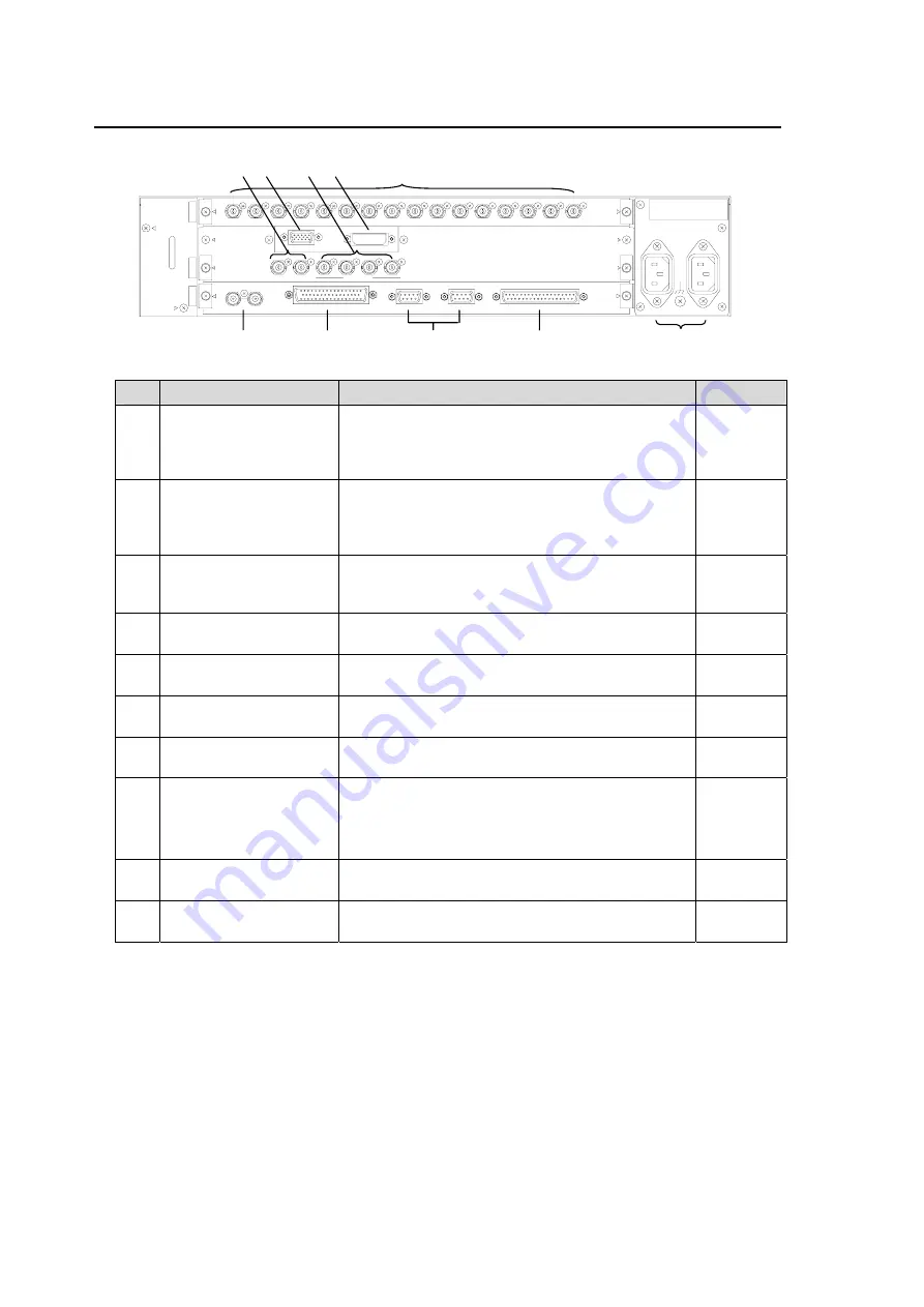
2-2. Rear Panel
No
Name
Description
Reference
(1) HD/SD IN
(INPUT1-16)
Used to input HD/SD SDI signal. Simultaneous
input of multi HD/SD formats is not supported.
Input signals should be synced with the
reference signal input to REF IN connector.
(2) HD/SD OUT
(OUTPUT1, 2)
Used to output HD/SD SDI signals for the main
screen in full or split screen. Menus are
displayed on these outputs. (Output signals
from OUTPUT1 and 2 are the same.)
(3)
HD/SD OUT
(FULL/QUAD
OUTPUT1 to 4)
Used to output HD/SD SDI signals for GROUP
display. Each GROUP is output to each
FULL/QUAD connector in full or quad mode.
(4) VGA OUT
(15-pin D Sub female)
Used to output Analog signal. Available when
the optional MV-160OUT is installed.
(5) DVI OUT
(24-pin DVI-D female)
Used to output Digital signal. Available when the
optional MV-160OUT is installed.
(6) REF IN
(Loopthrough)
Used to input external reference signal (black
burst or tri-level sync)
(7) TALLY IN
(50-pin D Sub female)
Used to input tally signal to add a red, green or
umber tally display on each input.
(8)
RS-232C
(9-pin D sub male)
RS-485
(9-pin D sub female)
Used to control from a PC.
(RS-485 is not in use.)
(9) REMOTE
(37-pin D Sub female)
Used to control the selection of full or split
screen display.
(10) AC-IN
Used to supply 100-240VAC (50/60Hz). Use
supplied cable.
-
HD/SD IN
CPU
AC100-240V 50/60Hz IN
2
1
VGA OUT
DVI OUT
REF IN
RS-232C
RS-485
TALLY IN
REMOTE
1
2
3
4
5
6
7
8
9
10
11
12
16
15
14
13
CP
U
INP
UT
FULL/QUAD
HD/SD OUT
1
2
4
3
1
2
RATING LABEL
OU
TP
U
T
(6)
(3)
(2) (1)
(7) (8)
(9)
(10)
(4)
(5)
Summary of Contents for MV-160HS Multi Viewer
Page 1: ...MV 160HS Multi Viewer 2nd Edition OPERATION MANUAL...
Page 2: ......
Page 6: ......
Page 45: ...MV 160HS Multi Viewer 4th Edition RS 232C COMMAND...
Page 46: ......
Page 48: ......
Page 64: ......


