background image

204 

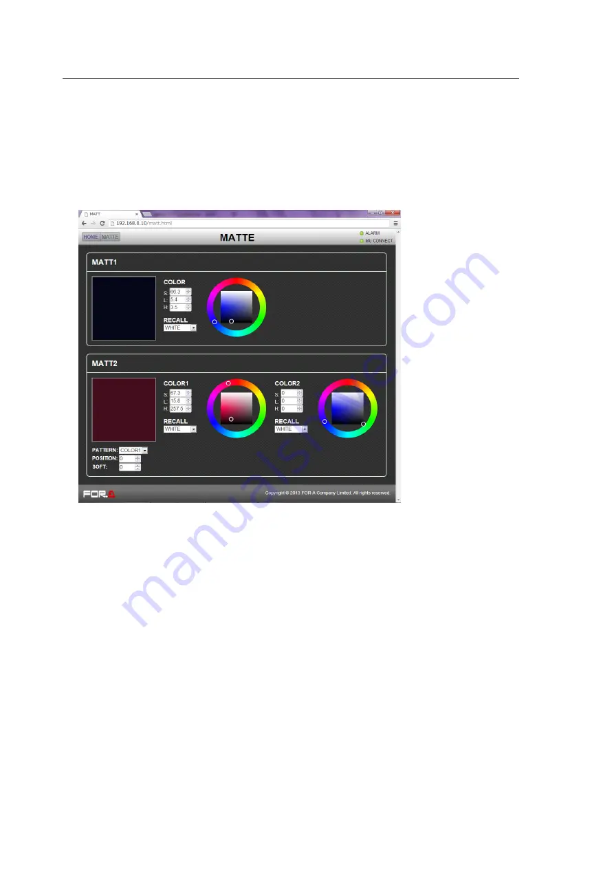
21-12. MATTE 

Click 

MATTE

 in the HOME screen to display the MATTE menu page. 

 See section 5-9. "Bus Matte" 

 
To Specify Color for MATT1 and MATT2 

 See section 5-9-1. "Setting the Matte Color." 

 
Select color by setting the 

HSL

 values, by selecting a preset color under 

RECALL

 or using the 

color circle. To set color on the color circle, specify 

Hue

 in the outer circle and 

Luminance

 and 

Saturation

 on the inner rectangle. 


To Specify Gradient Matte (MATT2 only) 

 See section5-9-2. "Setting the Gradient Matte."


(1) Select a start color for the gradadient matte under 

COLOR1

(2) Select an end color for the gradadient matte under 

COLOR2

(3) Select a pattern for the gradation matte under 

PATTERN

(4) Set the position at 

POSITION

 and adjust the softness gradient at 

SOFT


Summary of Contents for HVS-XT100

Page 1: ...HVS XT100 100OU HVS XT110 Digital Video Switcher 1st Edition OPERATION MANUAL...

Page 2: ...2 Edition Revision History Edit Rev Date Description Section Page 1 2013 08 30 1st edition...

Page 3: ...Ensure power cord is firmly plugged into AC outlet Operation Do not operate unit in hazardous or potentially explosive atmospheres Doing so could result in fire explosion or other dangerous results Do...

Page 4: ...y and disconnect power cord to avoid potentially hazardous conditions If problems similar to above occur contact authorized service representative before attempting to again operate unit Rack Mount Br...

Page 5: ...XT100ARC 1 Arcnet I F Card HVS XT100ED 1 Editor Control Software HVS XT110PSM 1 Redundant Power Supply Unit Rack Mount Brackets 1 set EIA standard type HVS XT100 Packing List HVS XT100 MU Box ITEM QTY...

Page 6: ...ction 10 m BNC 5C2V 75 About This Manual This manual is intended to help the user easily operate Hanabi series switchers and make full use of their functions during operation Before configuring or ope...

Page 7: ...ng Date Time and Time Zone at Initial Use 29 4 Menu Operation 30 4 1 How to Access Menus 30 4 1 1 Menu Access Buttons 30 4 1 2 Other Menu Access Buttons 31 4 1 3 USER Buttons Menu Shortcut 31 4 2 How...

Page 8: ...utput Link Groups 53 6 8 2 Creating Signal Link Groups 53 6 8 3 Enabling AUX LINK 54 7 Bus Operation 55 7 1 Selecting Video Sources 55 7 1 1 Selecting Video Sources on the PGM PST 55 7 1 2 Selecting V...

Page 9: ...K Layer Order 84 9 6 Mask and Invert 85 9 6 1 Inverting Key and Background 85 9 6 2 Key Masks 85 9 7 Key Edge 87 9 8 DVE Effects on KEY DSK 88 9 8 1 How to Enable 2D DVEs 88 9 8 2 Changing Position an...

Page 10: ...ng at Startup 114 12 4 Transferring Image Files 115 12 4 1 LAN Connection 115 12 4 2 Image files 116 12 4 3 Sending Receiving Still Images 118 12 4 4 Sending Images to Clip Memory 119 12 5 CG WIPE 120...

Page 11: ...4 Macro Execution Buttons 147 16 4 1 Changing KEY AUX Bus Buttons to Macro EXE Buttons 147 16 4 2 Macro Attach and Macro Detach 148 17 File Operation 149 17 1 USB Flash Drive 149 17 2 Available Files...

Page 12: ...1 20 3 3 Crosspoint Switches Using the Menu 181 20 3 4 Crosspoint Switches with Control Buttons Setup 182 20 3 5 Crosspoint Switches with Control Buttons Execution 183 20 3 6 Displaying Destination So...

Page 13: ...11 21 15 5 SETUP GPI TLY 212 21 15 6 SETUP FUNCTION 213 21 16 STATUS 213 21 17 EXT IF 214 21 17 1 EXT IF EDITOR Option 214 21 17 2 EXT IF TSL TLY 214 21 17 3 EXT IF VTR VDCP 214 21 17 4 EXT I F ROUTER...

Page 14: ......

Page 15: ...HD SD SDI 12 input 8 output and single HDMI output Redundant Power Supply with HVS XT110PSM option HVS XT100 XT110 Frame synchronizer on IN01 to IN08 Resizing engine on IN05 to IN08 Built in multivie...

Page 16: ...the KEY AUX bus No 7 6 7 9 13 1 6 KEY AUX Bus Used to select video for the bus selected in the BUS SELECT block No 6 The video can be selected from KEY AUX bus buttons PGM PREV CLEAN and MV 7 PGM PST...

Page 17: ...ON if redundant power supply is configured 2 POWER indicator Power indication is lit green when power switch is set to ON and power is applied to unit 3 ALARM indicator Indicates fan alarm status Norm...

Page 18: ...tput and Tally output 25 pin D sub female 20 1 1 9 AC IN1 Used for connection to AC power source via supplied accessory cord AC 100V 240V 50 60Hz Be sure to ground the protective earth terminal before...

Page 19: ...The video can be selected from KEY AUX bus buttons PGM PREV CLEAN and MV 7 PGM PST M E Bus Used to select video for the background 5 8 USER BUTTON User assignable buttons Menu shortcuts or functions...

Page 20: ...GPI input output and Tally output 25 pin D sub female 20 1 1 8 ARCNET Optional Arcnet LAN port HVS XT100ARC One port is used for HVS AUX bus Control Box connection The other port is used for loopthrou...

Page 21: ...20 6 Remote Panel HVS 30RU Tally Units See section 20 1 3 Sending Tally Signals to Tally Units VTR VDCP devices See section 20 2 VTR VDCP Control Routers See section 20 3 Router Control Editor See sec...

Page 22: ...Supplied LAN cable 75 terminator PGM AUX1 To AC power source Video server VTR etc TSG REF signal HD SD SDI HD SD SDI Preview AUX2 HVS XT100 rear panel REF OUT 1 1 2 3 4 5 6 7 8 2 3 4 A B C REF IN 1 2...

Page 23: ...rd 5 Slide the clamp on the ladder strap toward the plug 6 Fasten the clamp tightly 7 Gently pull on the AC cord to ensure it is secured Uninstallation 1 Push the tab on the retaining up to unfasten t...

Page 24: ...Web browser control Ethernet 21 PC Image transport Ethernet 12 4 GPI OUT TALLY OUT GPI Controller Web based control Image file transfer PC Router Multiview HDMI DC12V 1 2 POW ER OFF ON MODE SW TO MU H...

Page 25: ...2 Preview Set Up for details on displaying preview image REF OUT 1 1 2 3 4 5 6 7 8 2 3 4 REF IN HDMI OUT A UX 5 6 7 8 A UX LAN SDI INPUT 9 10 11 12 SDI INPUT GPI IN TA LLY OUT DC1 2V IN 1 2 MODE SW P...

Page 26: ...ARCNET LAN optional 20 5 Remote Panel HVS 30RU RS 422 20 6 PC Web browser control Ethernet 21 PC Image transport Ethernet 12 4 REF OUT 1 1 2 3 4 5 6 7 8 2 3 4 REF IN HDMI OUT AU X 5 6 7 8 AU X LAN GE...

Page 27: ...nd power cord to supply power to the HVS XT100OU Secure the DC cord to the HVS XT100OU rear panel with the supplied cord clamp See section 3 1 2 Installing the Power Cord Retaining Clamp 4 Turn on the...

Page 28: ...nu as shown below appears Turn F1 to select the signal format used in the switcher then press F1 6 Turn F3 to select the aspect ratio then press F3 For example to use HD SDI signals 1080i 59 94Hz set...

Page 29: ...change the date press F1 to select Month Day or Year then turn F1 to change the setting 4 If you need to change the time press F3 to select Hour Minute or Second then turn F3 to change the setting SYS...

Page 30: ...SETUP Accesses menu for sub effect channel settings TRANS RATE TRANS RATE Accesses menu for transition settings WIPE WIPE Accesses menu for WIPE pattern modification SELECT keypad Block Four modes but...

Page 31: ...AUX1 to AUX4 SETUP OUTPUT OUT XPT 1 3 menu PREV SET UP OUTPUT CLN PREV PREV menu CLEAN SET UP OUTPUT CLN PREV CLEAN menu MV SETUP OUTPUT MV menu Transition block See Fig Button Accessed Menu Page C BK...

Page 32: ...ple below Then press F1 or the page down button to the right to open the selected submenu SETUP SYSTEM INPUT OUTPUT PANEL MENU GPI TLY FUNCTION EXT I F STATUS 3 The SETUP INPUT menu then opens The SET...

Page 33: ...y window data is displayed over 2 lines A maximum of four parameters can be displayed at a time An or in front of a value indicates that it is possible to change a parameter setting by turning a menu...

Page 34: ...then press ENTER 7 To change the H Hue setting press F3 input the new setting from the keypad then press ENTER MATT1 BUS MATT1 COLOR RECALL 1 4 COLOR S 50 0 L 80 2 H 125 5 GREEN IMPORTANT When pressi...

Page 35: ...ction 9 8 DVE Effects on KEY DSK 2 Pressing WIPE POS on the Joystick block allows you to control parameters via the joystick without opening the menu How to Use the Joystick Users can simultaneously p...

Page 36: ...ection 19 2 System Initialization WIPE MODIFY menu Each submenu in the WIPE MODIFY menu KEY SETUP menu Each submenu in a KEY SETUP menu CHR KEY SETUP menu The CHR KEY SETUP menu EFFECT SETUP menu Each...

Page 37: ...01 to INPUT08 SDI video input to rear connectors 1 8 XT110 IN01 to IN12 IN01 to IN12 INPUT01 to INPUT12 SDI video input to rear connectors 1 12 STILL1 STILL2 STL1 STL 2 STILL1 STILL2 Still images 1 2...

Page 38: ...sft20 shifted buttons SIGNAL NAME IN01 See the table below INHIBIT OFF OFF ON BUTTON SIGNAL setting Description Refer to 01 to 12 sft01 to sft12 shifted buttons NONE No signal assignment BLACK Black s...

Page 39: ...AUTO or SD SDI for FORMAT 5 Turn F3 to select an aspect ratio under RESIZE INPUT SELECT FORMAT RESIZE FS 1 4 SIGNAL IN05 SD SDI 4 3 ON IMPORTANT The Resize function is automatically enabled when SD s...

Page 40: ...down button to display the submenu 3 Turn F1 to select USER BTN then press F1 or the page down button to display the SETUP PANEL USER BUTTON 1 2 menu 4 Turn F1 to select OU 1 OU USER 1 USER 1 will bl...

Page 41: ...lor 8 Turn F4 to select a color from the following 8 standard colors Then press F4 to apply the setting If you want to adjust the selected color or set the color by entering its HSL values See section...

Page 42: ...ct OU 3 OU USER 3 USER 3 will blink 3 Turn F2 to select OTHER Turn F3 to select FS ENABLE USER SELECT TYPE FUNC F3 1 2 BUTTON OU 3 OTHER FS ENABLE Enabling FS for IN01 While holding down USER 3 press...

Page 43: ...1 00 0 ON 6 Press the page down button to go to PAGE 2 7 You can adjust the chrominance level under ChmGain and the color under Hue INPUT SELECT ChmGain Hue ENABLE 2 3 PROC AMP IN04 10 00 0 0 ON 5 8...

Page 44: ...anging Settings or Values Using the Joystick Parameter Setting Range Description Joystick operation S Saturation 0 0 to 100 0 Adjusts color saturation Moves Joystick horizontally X axis L Luminance 0...

Page 45: ...TERN setting Description COLOR1 Displays the matte color set at BUS MATT2 COLOR1 H Displays a horizontal gradient from COLOR1 to COLOR2 V Displays a vertical gradient from COLOR1 to COLOR2 H V Display...

Page 46: ...utton in the KEY AUX bus section to select a signal for the selected AUX output AUX5 to AUX8 bus buttons can be assigned to USER buttons See section 14 USER Buttons 6 1 2 Selecting Video from Menu Sel...

Page 47: ...using crossfade transitions This chapter explains how to switch AUX video using an operational example Ex Changes the AUX1 video in 30 frames using a crossfade 1 Double press AUX1 on the left side of...

Page 48: ...to display the SETUP OUTPUT CLN PREV 2 2 menu 2 Turn F1 to F4 to set whether the key images are to be displayed on the preview image then press the push button to confirm the setting for each OUTPUT...

Page 49: ...tting 3 Set KEY2 and DSK1 2 in the same way OUTPUT KEY1 KEY2 DSK1 DSK2 1 2 M E CLN ON ON ON ON 6 4 KEY OUT Set Up The KEY OUT signal switcher processed key cut signal alpha channel can be assigned to...

Page 50: ...able options are PGM PREV CLEAN MEKY and AUX1 8 and MV System Format Output signal format 1080i HDTV 1920 x 1080 720p HDTV 1280 x 720 SD SDTV 720 x 480 Signals are output at the same frequency as that...

Page 51: ...em in the SETUP OUTPUT MARKER menu from BOX and HOOK See the figures at the bottom of the page Then go to PAGE 2 select an aspect ratio and set the marker size OUTPUT SELECT ENABLE MARKER SIDECUT 1 2...

Page 52: ...in HD mode 6 7 1 Passing Incoming Ancillary Data on through to AUX Outputs 1 Open the SETUP OUTPUT ANCI menu PAGE 2 2 Turn F1 to select an output then turn F2 to set to ON pass OUTPUT SELECT ENABLE 2...

Page 53: ...serving as the MASTER Available outputs are shown below Master Output AUX1 8 PGM PST ABUS BBUS KEY1 KEY2 DSK1 DSK2 5 Select the auxiliary outputs up to three serving as the SLAVE linking to the MASTER...

Page 54: ...LINK groups FUNCTION ENABLE 1 3 AUX LINK ON Operation examples Assume that the AUX output link groups and their signal link groups were set as shown below SELECT MASTER SLAVE SEL AUX 2 3 AUX GRP 1 AUX...

Page 55: ...ut screen Then move the fader lever from end to end to check how the button indication changes as the signals are switched Once the transition is complete the selected signals on PGM and PST are switc...

Page 56: ...ile holding down KEY1 press 5 in the KEY AUX bus to select the KEY1 Source signal Once insert and source signals are selected for a key or DSK they are stored as a key pair and when a key or DSK then...

Page 57: ...BUSTYPE FADER OFFSET 1 1 M E CTRL A B U 1 00 L 1 00 7 3 Setting up and Using the SHIFT Function Users can select a video signal from 12 sources on the control panel because each bus row has 12 buttons...

Page 58: ...on 12 SHIFT function Now let s select IN01 on PGM and STILL1 on PST When SHIFT works in NORMAL mode Shifted buttons are enabled while holding down SHIFT When SHIFT works in TOGGLE mode To select shift...

Page 59: ...ons setup by next transition bus selection Transitions using the AUTO button or fader lever More than 130 types of various preset patterns Simultaneous background and key pattern transitions Transitio...

Page 60: ...button Available BKGD MIX Fader lever WIPE Available Available NOR REV BKGD WIPE AUTO button 8 3 8 8 Available NOR REV BKGD WIPE Fader lever KEY1 KEY2 CUT Available KEY CUT button KEY1 and KEY2 transi...

Page 61: ...splayed If the light of the WIPE button does not turn on a WIPE channel is already being used for KEY1 or KEY2 In such case change the KEY1 or KEY2 type to MIX then press the WIPE button again for the...

Page 62: ...e See section 8 11 3 Transition Limit for the transition limit To Check Next Video To check the Preview video assign the Preview video to an AUX bus to display the image See section 6 2 Preview Set Up...

Page 63: ...UTO or KEY1 or move the fader lever to perform the KEY1 MIX transition Pattern transition 1 Press KEY1 in the NEXT TRANSITION block 2 Press WIPE in the TRANSITION TYPE block The TRANS 1 6 menu is disp...

Page 64: ...s on WIPE transitions See section 8 11 2 Transition Rate for details on the transition rate See section 8 11 3 Transition Limit for details on the transition limit Note that when performing pattern tr...

Page 65: ...transition scaler slide in out etc is assigned to insert the DSK1 image on the M E program video See section 8 10 2 USER Transitions for details 8 5 1 Where DSK Images Appear The DSK1 and DSK2 images...

Page 66: ...tton allows BLACK transitions to be performed Pressing the button initiates a fade to black of whichever source is currently on air program output Pressing the button again starts another fade from bl...

Page 67: ...is being used by CG WIPE See section 12 5 CG WIPE 2 Turn F4 to select a pattern The Direct Pattern function allows users to select patterns quickly See section 8 8 3 Direct Pattern Function Available...

Page 68: ...us Deselect WIPE in another bus and set WIPE again for the bus Note that 2D DVE menu settings are all disabled while a pattern transition is being performed on KEY1 or KEY2 See section 9 8 DVE Effects...

Page 69: ...The keypad also changes to DIRECT PATTERN mode 4 Turn F1 to select PAGE 0 if it is not selected DIRECT PAGE DIRECT CLEAR 1 1 PATTERN 0 ON OFF 5 Press STORE in the Keypad 6 Press 1 in the Keypad If a P...

Page 70: ...selected 3 Press 1 on the Keypad The DIRECT RECALL menu will be displayed 4 Turn F3 to change OVER WR Overwrite to DISBL Disable to set overwrite protection DIRECT PATTERN OVER WR DELETE 1 1 RECALL 02...

Page 71: ...erse operation Lit Unlit Reverse at Normal Reverse operation Lit Lit Transition Rate The AUTO transition duration Transition Rate can be set in the menu See section 8 11 2 Transition Rate Transition L...

Page 72: ...as shown below TRANS RATE TRANS LIMIT PAT NO 1 6 BKGD 30 100 0 OFF M0 The following chapters explain how to modify patterns using the background and KEY1 as examples 8 9 1 WIPE Type No 0 99 WIPE menu...

Page 73: ...under WIDTH and border softness under SOFT WIPE SIGNAL WIDTH SOFT 1 2 BORDER MATT 5 0 2 0 8 Press the page down button to go to PAGE 2 9 Turn F4 to select a border color among eight standard colors S...

Page 74: ...ll be reset to its default settings 8 9 2 DVE Type No 100 137 WIPE menu The pattern number is displayed instead of 1XX in the top page of the submenu WIPE BORDER POS ASP CROP CG WIPE No 1XX INIT WIPE...

Page 75: ...ample To add a border set the border width under INSIDE X and Y WIPE INSIDE OUTSIDE 1 3 BORDER X 20 Y 50 X 0 Y 0 7 Press the page down button to go to PAGE 2 Set the softness for the inside border und...

Page 76: ...ons The transition buttons turn on while On Air and turn off when Off Air The light up color of DSK buttons indicates the output destination M E or AUX bus Transition state Output bus Transition butto...

Page 77: ...itions 8 10 2 USER Transitions The Key and DSK transition functions can be assigned to user buttons This chapter explains how to assign functions to buttons by assigning DSK1 SCALER to USER BUTTON 3 a...

Page 78: ...ttons in the transition block can also open the related TRANS menu page BKGD KEY1 KEY2 NEXT TRANSITION butons on the left side of the fader MIX WIPE TRANSITION TYPE buttons TRANS RATE TRANS LIMIT PAT...

Page 79: ...e 100 0 and OFF With this setting the transition is complete with fully switching pictures In the following menu pages the transition limit for KEY1 2 and DSK1 2 can be set in the same way 8 11 4 Adju...

Page 80: ...lable 9 1 Full key Available Available 9 2 Bus key Available Available 9 3 Key invert Available Available 9 6 1 Box mask signal mask Available Available 9 6 2 Preset mask Available 9 6 2 Edge effect A...

Page 81: ...s F1 or the page down button KEY1 INS SRC EDGE MASK SETUP POS SIZ BORDER INIT 5 The KEY1 INS SRC menu is displayed Turn F1 to set TYPE to LUM The insert signal can also be selected at INSERT KEY1 TYPE...

Page 82: ...NK function which enables you to select a key source and insert using only a source button See section 9 3 1 Key Link for details 1 Press KEY1 above the KEY AUX bus 2 Select a signal for Key Insert in...

Page 83: ...NCTION M E_KEY menu 9 3 2 KEY INSERT MATT In addition to the bus matt signal the internally generated MATT can be used as key fill KEY INSERT MATT is a dedicated matte signal for keys and it is not th...

Page 84: ...be set for Bus and Luminance keys 7 Go to PAGE 3 8 Set key luminance thresholds levels under CLIP H and CLIP L Turn F3 to ON to enable these limits KEY1 CLIP H CLIP L ENABLE 3 4 KEY CLIP 100 0 0 0 ON...

Page 85: ...e 1 Create KEY1 2 Double press KEY1 above the KEY AUX block to display the KEY1 SETUP menu 3 Turn F1 to select MASK and press F1 or the page down button to open the KEY1 MASK menu 4 Turn F2 to set BOX...

Page 86: ...UX5 INV ON Preset Mask WIPE patterns can be used for mask signals for KEY1 and KEY2 1 Open the KEY1 MASK menu PAGE 1 See the previous page 2 Turn F3 to select PST PRESET 3 If you want to invert a key...

Page 87: ...display outlines without key fill images 2 The SOFT parameter is for setting softness TRANSP is for transparency and WIDTH is for edge width KEY1 TYPE SOFT TRANSP WIDTH 1 3 EDGE O_LIN 0 0 1 3 Press t...

Page 88: ...DVE function is enabled for KEY1 and therefore the POS SIZE and BORDER menus for KEY1 become available If 2D DVE cannot be set to ON Up to 4 channels of DVE can be assigned to BKGD KEY1 2 and DSK1 2...

Page 89: ...block to display KEY1 POS SIZE menu PAGE1 2 Turn F1 or F2 to set the position of the KEY1 image KEY1 POSITION SIZE 2D DVE 1 5 POS SIZE X 0 Y 0 500 ON 3 Turn F3 to set the size of the KEY1 image KEY1 P...

Page 90: ...ECT FADE LV 2 5 ASPECT X 1000 Y 1000 0 0 The figures below are examples when POSITION is set to 0 0 9 8 4 FADE FADE allows users to add an effect to make backgrounds transparent 1 Go to the KEY1 POS S...

Page 91: ...Rotates around the Y axis Y Rotation Rotates around the X axis Z Rotation Rotates around the origin In the factory default setting the base point coordinates 0 0 0 coincide with the center point of t...

Page 92: ...enter a negative number enter the number press then press ENTER 2 Change the center of rotation on PAGE4 of the KEY1 POS SIZE menu To rotate the key image at the current POSITION leave CENTER POSITIO...

Page 93: ...KEY1 POS SIZE menu KEY1 CROP POSITION 5 5 CROP T 0 B 0 L 0 R 0 2 Use F1 F2 F3 and or F4 to crop the KEY1 image POSITION 200 200 SIZE 500 CENTER POSITION 150 200 400 LOCAL ROTATION 0 0 100 Point of vie...

Page 94: ...ess of the outer half of the border is set at OUTSIDE KEY1 INSIDE OUTSIDE 2 3 BDR SOFT X 0 Y 0 0 4 Press the page down button to go to PAGE3 Turn F4 to select a color among eight standard colors then...

Page 95: ...omakey Setting Up KEY1 1 Select a signal to be used as a background on the PGM bus 2 Double press KEY1 above the KEY AUX block to display the KEY1 SETUP menu 3 Turn F1 to select INS SRC and press F1 o...

Page 96: ...esired color To precisely adjust the position turn F1 and F2 to set POSITION X and Y Selecting a darker color makes adjustment easier 7 To create a chromakey turn the SIZE control in the joystick coun...

Page 97: ...mage return the setting to OFF LUM CORING Effective for areas illuminated un uniformly GREEN CORING Effective for areas that are colored green unevenly BLUE CORING Effective for the areas that are col...

Page 98: ...e Foreground is not high enough Gradually increase the SOLIDNESS value about 10 for each in PAGE 2 and repeat Steps 2 and 3 10 2 2 Adjusting the Foreground Image Chromakey Color 1 Foreground FILL Coar...

Page 99: ...e the SOLIDNESS value about 10 levels for each setting and repeat Step 2 10 2 3 Adjusting Edges EDGE SHRINK and EDGE REPLACE parameters allow users to adjust chromakey edges To Shrink Foreground Edges...

Page 100: ...scription DENSITY 0 100 to 100 Reduces edge spills reflections between foreground and background adjusting the density or solidness of the reference color SOLIDNESS 0 100 to 100 WHITE 0 100 to 100 Fin...

Page 101: ...reground boundary L OFF OFF ON Setting ON narrows the left hand boundary of the foreground R OFF OFF ON Setting ON narrows the right hand boundary of the foreground POST FILTER H OFF OFF ON Smoothes t...

Page 102: ...the contrast ratio bright parts become brigher and dark parts become darker based on the back color luminance level EDGE REPLACE T OFF OFF ON Setting ON change edge colors to the foreground object col...

Page 103: ...bus to display the menu 3 Turn F2 to set INSERT to CKFL and turn F3 to set SOURCE to CKKY DSK1 TYPE INSERT SOURCE INVERT 1 4 INS SRC BUS CKFL CKKY OFF 4 Press DSK1 in the transition block to display D...

Page 104: ...ess MENU then EFFECT in the SELECT KEYPAD block to display the EFFECT SETUP top menu 2 Turn F1 to select SUB EFF1 or SUB EFF2 then press F1 or the page down button to display the submenu EFFECT SUBEFF...

Page 105: ...effects are also available 1 Display SUB EFFECT1 PAGE 3 SUB EFF1 FREEZE STROBE NEGA MOSAIC 3 3 FREEZE OFF OFF OFF OFF 2 When applying these effects refer to the table below Parameter Description FREEZ...

Page 106: ...en STILL in the SELECT KEYPAD block to display the menu 2 Select PGM under FILL SOURCE and KEY SOURCE 3 Then press F1 to save the image to STILL1 A beep will sound and the image will be saved to the s...

Page 107: ...the STILL menu 2 Turn F1 to select STIL1 or STIL2 to be loaded 3 Turn F2 to select LOAD 4 Turn F3 to select the memory number where the desired still image is stored 5 Press F2 to load the still from...

Page 108: ...g Recording Video Let s record the AUX1 video to a clip through STILL1 1 Press MENU then STILL in the SELECT KEYPAD block to display the STILL menu 2 Turn F1 to select CLIP under STILL1 3 Turn F3 and...

Page 109: ...REC PLAY F 0 7 Press F2 STOP or F4 PAUSE to stop recording Loop Recording Loop recording automatically loops back to the memory start point when it reaches the end of the memory and continues recordin...

Page 110: ...on KEY1 This example shows how to play the video and key clip recorded in the previous section Assume an animation logo V K as shown at right is stored in STILL2 Let s insert the logo through KEY1 th...

Page 111: ...5 in the STILL menu Turn F1 to select STL2 STILL2 and set LOOP to ON STILL SELECT LOOP REC MOD CLEAR 5 5 CLIP STL2 ON STD OFF F 100 10 Go to PAGE 4 in the STILL menu 11 Press F4 PLAY The logo animatio...

Page 112: ...emory device is displayed at the bottom right hand side in the FILE menu 12 3 1 Structure for Backing Up Still and Clip Data Standard Backup Memory MEM1 4 and USB Flash Drive for Backup Four backup re...

Page 113: ...elow A new subfolder will be created 12 3 2 Setting Automatic Backup to ON 1 Insert a USB memory stick for backup into the USB port on the switcher 2 Press MENU then STILL in the SELECT KEYPAD block t...

Page 114: ...hich the backup data is stored into the USB port 2 Open STILL menu PAGE 2 3 Turn F1 to select a still input still clip or all data to be loaded 4 Turn F4 to change RESUME to BACKUP In the setting exam...

Page 115: ...nect to the PC use a cross over cable Switcher Network Settings Open the SETUP SYSTEM ETHERNET menu The default settings for IP address Net mask and Default Gateway are as shown below SYSTEM IP ADDRES...

Page 116: ...es Setting the IP Address in Windows 7 Go to Start Control Panel Network and Internet Network and Sharing Center and then click Change adapter settings Right click the Local Area Connection icon and c...

Page 117: ...ta to the connected USB flash drive CLIP1 CLIP2 Used for uploading backup movie clips sequential files to STILL1 and 2 Each folder should contain only one clip STILL1 STILL2 Used for uploading backup...

Page 118: ...hanged Password fora Password cannot be changed 7 Once you have accessed the FTP server the following folders will be displayed in the window STILL1 and STILL2 CLIP1 and CLIP2 STILL IN01 to STILL IN08...

Page 119: ...50p 000 to 998 NTSC PAL yyy Indicates a file extension bmp jpg or tga WARNING STILL must be in upper case 2 Connect to the PC referring to steps 1 to 7 in the previous page Uploading Sequential Images...

Page 120: ...uences To play CG wipes the CG WIPE clip must be saved to a still buffer and a key channel is required for CG display Fig 1 CG WIPE Sequence Diagram with CG Key and Background Fig 2 Example of CG WIPE...

Page 121: ...or CG WIPE 4 Modify the selected pattern suitable for your CG WIPE sequence Setting up CG WIPE 1 Display the WIPE menu by pressing MENU then WIPE in the SELECT KEYPAD block 2 Display the WIPE CG WIPE...

Page 122: ...F OFF ON Sets CG WIPE ON OFF CG STL1 STL1 2 Selects a channel through which a CG is played back A DUR 30 0 to clip duration Sets the CG playback time C 2 3 SELECT KEY1 KEY1 2 Selects a KEY through whi...

Page 123: ...This chapter uses AUX2 4 way screen PGM PREV IN01 and IN02 display as examples 13 1 Assigning the Multiviewer to an Output Bus The multiviewer image can be assigned to any output bus AUX1 8 and HDMI...

Page 124: ...IN01 SHORT OUTPUT SCREEN SIGNAL CHARA 2 7 MV 2 IN02 SHORT OUTPUT SCREEN SIGNAL CHARA 2 7 MV 3 PVW SHORT OUTPUT SCREEN SIGNAL CHARA 2 7 MV 4 PGM SHORT Available video signals Input images XT100 IN01 IN...

Page 125: ...button to go to PAGE 4 OUTPUT SCREEN TITLE AREA POSITION 4 7 MV TITLE 1 NORML X 0 Y 100 Turn F1 to select a screen number split area Turn F2 to select the width of the title background Item Descriptio...

Page 126: ...for each screen 1 Open PAGE 3 in the SETUP OUTPUT MV menu 2 Turn F1 to select a screen number 3 Turn F2 to select audio channels to be displayed OUTPUT SCREEN AUDIO SF AREA SIZE 3 7 MV 1 Ch1 4 OFF AU...

Page 127: ...MARKER KEY TLY 6 7 MV TALLY ON ON ON Setting Example Here we assume that IN02 is displayed in the PGM screen and IN01 is selected on the PST bus The tally frame and marker are displayed on the screen...

Page 128: ...o the selected memory number OUTPUT DIV USER PRESET 1 7 MV 4 U1 SAVE 13 5 2 Loading a Screen Layout 1 Open PAGE 1 in the SETUP OUTPUT MV menu 2 Turn F3 to select the memory number 3 Turn F4 to select...

Page 129: ...above the FILE LOAD menu page is assigned to USER 1 Pressing USER1 directly opens the menu page To Assign Other Functions Assign a function to a user button in the same way as those for menu pages abo...

Page 130: ...Setting Function Button Indication GPI IN ENABLE Pressing the button enables GPI IN ON Lit orange OFF Lit white GPI OUTPUT1 8 PUSH The GPI OUTPUT function 1 8 represents the ON OFF setting for each GP...

Page 131: ...ARK IN VDCP MARK OUT VDCP TC DISPLAY Displays time code information when controlling VDCP devices Always lit white VTR1 2 SELECT Selects a VTR or VDCP channel for control Selecting the channel again d...

Page 132: ...Off AUX LINK ENABLE Enables all AUX links When OTHER is selected for TYPE Setting Function Button Indication EDITOR ENABLE Sets editor control On Off ON Lit orange OFF Lit white WIPE MOD RESET Resets...

Page 133: ...the menu as shown below 1 Open PAGE 1 of the USER BUTTON menu 2 Select OU 1 for SELECT USTRS for TYPE and KEY1 SCALER in the next field USER SELECT TYPE FUNC F3 1 2 BUTTON OU 1 USTRS KEY1 SCALER 3 Pr...

Page 134: ...User button function is activated when the state of the specified item changes to ON OFF User button function is activated when the state of the specified item changes to OFF DBL User button function...

Page 135: ...current panel settings to an event EVENT 12 PAGE1 Number Button 2 as an example 1 Press EVENT in the SELECT KEYPAD block The EVENT MEMORY menu is displayed and the keypad switches to EVENT mode 2 Turn...

Page 136: ...g 2 on the keypad to recall the event Selecting Data to be Loaded If DIRECT is set to OFF in the EVENT MEMORY menu you can select the data to be loaded in all settings saved in the event Now let s rec...

Page 137: ...EVENT OVER WR DELETE 3 3 RECALL DISBL OFF P 01 To delete data from EVENT 12 turn F2 to set DELETE to ON then press F2 EVENT OVER WR DELETE 3 3 RECALL OFF ON P 01 To Delete Data for an Event Page 1 Pre...

Page 138: ...ved to events If set DATA to OFF and XPT to OFF No data for the bus is saved to events XPT ON OFF DATA ON OFF RATE OFF 1 999 See section 15 5 Transitions Using Event Recall AUX SEL ALL AUX1 AUX8 Selec...

Page 139: ...he default settings in the EVENT MEMORY menu Only highlighted items are changeable EVENT PAGE DIRECT PAGECLR RATE 1 2 MEMORY 0 OFF CRNT OFF L 0 EVENT AUX BUS DSK ASG CG WIPE 2 2 MEMORY OFF OFF OFF L 0...

Page 140: ...0 19 EVENT PAGE DIRECT PAGECLR RATE 1 2 MEMORY 1 OFF CRNT OFF L 0 3 Press STORE to display the EVENT STORE menu 4 Press F4 enter 150 in the keypad then press ENTER EVENT SELECT XPT DATA RATE 1 2 STORE...

Page 141: ...US 4 The SETUP SYSTEM menu as shown below appears Turn F1 to select INIT and then press F1 to display the SETUP SYSTEM INIT menu SETUP FORMAT REF I O ARCNET ETHERNET SYSTEM RS 422 TIME INIT REBOOT 5 T...

Page 142: ...recording 4 Perform the operational procedures that you want to record as a macro 5 Press STORE again to stop recording 6 Press 2 on the keypad to store the macro If a Macro Is Already Saved to 2 on...

Page 143: ...M for AUX1 Select PREV for AUX2 Press the KEY1 transition button 1 Press MACRO in the SELECT KEYPAD block 2 Press STORE on the keypad to start recording 3 Press AUX1 above the KEY AUX bus 4 PressPGM 5...

Page 144: ...anged macros memorize the last stopped position Therefore to perform the same actions as those recorded with a fader return the fader to its previous position before a macro is executed 16 2 3 Operati...

Page 145: ...MCR 29 by default Names for registered macros can be changed using the menu as shown below Up to 6 characters are available 1 Press MACRO in the SELECT KEYPAD block to display the MACRO MEMORY menu a...

Page 146: ...Turn F2 to set to ON then press F2 The data stored in the memory button will then be cleared MACRO OVER WR DELETE NAME MCR01 1 1 RECALL ENBLE ON STEP 60 To Delete Data for a Macro Page 1 Press MACRO...

Page 147: ...Buttons Any macros can also be assigned to the KEY AUX bus buttons as shown below 1 Press MACRO in the SELECT KEYPAD block 2 The MACRO MEMORY menu will appear Go to PAGE 3 3 Turn F1 to select a KEU A...

Page 148: ...ve the Macro from DSK1 1 Press MACRO 2 Press DETACH on the keypad 3 Press DSK1 in the transition block You can also press other buttons to be detached here 4 Press DETACH on the keypad again SIZE PUSH...

Page 149: ...Still 1 to Still 2 capture video in jpg format tga 2 tga TARGA format files uncompressed RGB STILL1 tga to STILL2 tga Still 1 to Still 2 capture video in targa format bmp 2 bmp Bitmap format files unc...

Page 150: ...sound will be heard when the data is saved If the same file exists in the USB flash drive A pop up window appears and asks if you would like to overwrite the existing file Turn F3 to select CANCEL OV...

Page 151: ...off then powered ON The system data is applied only after the switcher is restarted Be careful when loading system data setting files with all or sys file extension because the switcher cannot connect...

Page 152: ...put To display the input video again on the input bus perform CLEAR in the INPUT STILL menu See section 5 4 INPUT STILL Freezing Input Video 17 5 Moving between USB Flash Drive Directories USB flash d...

Page 153: ...to 16 alphanumeric characters for any file stored to USB flash drive Existing files can also be named renamed using the following procedure 1 Open the FILE LOAD menu If you are in the FILE SAVE menu p...

Page 154: ...R button in the SELECT KEYPAD block to reboot the system SETUP FORMAT REF I O ARCNET ETHERNET SYSTEM RS 422 TIME INIT REBOOT 7 The selected system format is applied to the switcher after rebooting 18...

Page 155: ...SETUP SYSTEM REF OUT menu 2 Turn F1 to select a reference signal to be output from the switcher between Black Burst and Tri level Sync 3 You can adjust the horizontal phase of the reference signal un...

Page 156: ...PAGE 3 2 Press F1 to highlight the first octet 192 in the menu example below of the IP address SYSTEM SNTP SERVER IP ADDRESS UPDATE 3 4 TIME 192 168 000 011 EXEC 3 Turn F1 to change the value and pre...

Page 157: ...u You can also set the buzzer On Off and the start time of the screen saver shown on the menu display 1 Open the SETUP PANEL menu SETUP UTILITY TRS CTRL USER BTN PANEL 2 Turn F1 to select UTILITY then...

Page 158: ...rking properly ERR Indicates a FAN has failed Power off the switcher and consult your FOR A reseller GENLOCK External Lock Indicates a valid reference signal is present and video signals are properly...

Page 159: ...sion SOFT OU HVS XT100 110 Software version SOFT RU HVS 30RU Software version FPGA MU GL HVS XT100 110 FPGA firmware version for Genlock FPGA MU ME HVS XT100 110 FPGA firmware version for ME FPGA MU S...

Page 160: ...tes Upgrade Files for HVS 30RU RUB For HVS 30RU software updates 18 7 1 Upgrade Procedure Once the system is upgraded all setting data will be lost and return to their factory default settings Importa...

Page 161: ...completed COMPLETE will appear on the display 9 Restart the switcher to complete the upgrade IMPORTANT Upgrade your switcher system with other upgrade files in the same manner as that of the above pr...

Page 162: ...nu SETUP FORMAT REF I O ARCNET ETHERNET SYSTEM RS 422 TIME INIT REBOOT 4 Turn F1 to select SETUP expSYS then press F1 to initialize the switcher setup data aside from the system data SYSTEM INIT LOAD...

Page 163: ...2 KEY1 AUTO TRANS input default setting 3 KEY2 AUTO TRANS input default setting 4 DSK1 AUTO TRANS input default setting 5 DSK2 AUTO TRANS input default setting 6 24 No assignment default setting 25 Fr...

Page 164: ...ns are simultaneously performed Up to 60 pairs of pin and function can be set See section 20 1 4 GPI Tally Function List GPI Inputs Ex 1 Performs background AUTO transitions using PIN 2 Ex 2 Performs...

Page 165: ...the GPI I O menu See section 14 USER Button for details on how to assign the function to the USER button GPI Outputs Ex 3 Outputs GPI signals from PIN 9 while BKGD transitions are being performed To...

Page 166: ...en turn F2 to select GRN GPI TLY SELECT COLOR 1 1 TLY COL PGM RED GPI TLY SELECT COLOR 1 1 TLY COL PST GRN Assigning Tallies to PIns 1 Open PAGE 1 in the SETUP GPI TLY GPI I O menu 2 Turn F2 to select...

Page 167: ...automatically set according to the tally unit SYSTEM SELECT FUNC BAUD PARITY 1 1 RS 422 PORT2 TALLY 38400 EVEN 4 Restart the switcher See section 19 1 Rebooting System Tally Unit Settings The followin...

Page 168: ...Y1 CUT TRANS TYPE KEY2 CUT Changes KEY transitions to CUT type TRANS TYPE DSK1 MIX TRANS TYPE DSK2 MIX Changes DSK transitions to MIX type TRANS TYPE DSK1 CUT TRANS TYPE DSK2 CUT Changes DSK transitio...

Page 169: ...d Off XPT AUX1 8 BLACK Selects BLACK for an AUX bus XT100 XPT AUX1 8 IN01 08 Selects a primary input for an AUX bus XT110 XPT AUX1 8 IN01 12 Selects a primary input for an AUX bus XPT AUX1 8 STILL1 2...

Page 170: ...RANS DSK2 AUTO TRANS Outputs pulse while KEY DSK AUTO transitions are processed TRS TYPE BKGD CUT Outputs pulse while the BKGD transition type is set to CUT TRS TYPE KEY1 CUT TRS TYPE KEY2 CUT Outputs...

Page 171: ...0 RED TALLY IN01 12 RED TALLY STIL1 2 RED TALLY STILK1 2 RED TALLY MATT1 2 RED TALLY CKFIL RED TALLY CKKEY RED TALLY EFF1 2 RED TALLY PGM RED TALLY PREV RED TALLY CLN GREEN TALLY BLACK Outputs a green...

Page 172: ...onnecting a VTR to RS 422 1 port set the menu as shown below If your device supports VDCP protocol set VDCP1 instead of VTR1 under FUNC SYSTEM SELECT FUNC BAUD PARITY 1 1 RS 422 PORT1 VTR1 38400 ODD 5...

Page 173: ...ect the VDCP model type See the table below MODEL setting Description Mira Abekas Mira Servers HVS 5ECD FOR A HVS 5ECD Playing and Recording on the VTR Playback and Recording on the VTR can be control...

Page 174: ...s Rewinds or fast forwards tapes or other video storage media F4 Turn Switches between REW and FF 3 4 CUE UP F1 Press Cues up to a location specified by time code value Set the time code value in the...

Page 175: ...d from connected device Copying and clearing Playlists The switcher can create new Clips See page 178 Creating New Clips Note that some VDCP devices may not support all commands available on the switc...

Page 176: ...opy and paste the current time code MARK IN MARK OUT F1 Press Press F1 The current time code is copied into the time code field Adjust time code on a per frame basis F2 Turn Turn F2 to increase or dec...

Page 177: ...decrease fames then press F3 3 Press F1 CUE UP to jump to the specified point EXT I F 00 00 00 00 3 7 VTR VDCP CUEUP TC 00 00 00 00 Changing CLIP ID Mira only 1 Press F2 in PAGE 5 of the SETUP EXT I F...

Page 178: ...T I F VTR VDCP menu 2 Set 1 or 2 under SELECT to select Playlist 1 or 2 for copying data 3 Turn F4 to select COPY and then press F4 EXT I F SELECT FUNC 5 7 VTR VDCP 1 ID SET TC SET COPY 4 Turn F1 to s...

Page 179: ...t to ON press F4 to start recording If DIRECT REC is set to OFF press PLAY while holding down REC in PAGE 2 to start recording Recording will automatically stop when the duration time is elapsed EXT I...

Page 180: ...EM SELECT FUNC BAUD PARITY 1 1 RS 422 PORT2 ROUTER 57600 NONE 3 After settings are complete reboot the switcher See section 19 1 Rebooting System RS 422 ROUTER REF OUT 1 1 2 3 4 5 6 7 8 2 3 4 REF IN H...

Page 181: ...turn F4 to set the title link display to ON or OFF 20 3 3 Crosspoint Switches Using the Menu To execute the following commands Select a router level Connect Source channel 2 to Destination channel 1...

Page 182: ...4 USER Buttons for details on user button assignments Router Control Button Settings Router control level and button settings are set as shown below as factory default settings Level to be controlled...

Page 183: ...same way press AUX2 5 Then press 4 on the KEY AUX bus 20 3 6 Displaying Destination Source Settings The switcher can obtain and display the current destination source settings crosspoints on the route...

Page 184: ...t to store the data and the message DATA SAVING is displayed on the display EXT I F LOAD SAVE 5 6 ROUTER 3 After saving is complete the message COMPLETED is displayed Loading Crosspoints 1 Go to PAGE5...

Page 185: ...ter the preset has been changed in the router 2 is displayed under SRC EXT I F LEVEL DEST SRC TAKE 3 6 ROUTER 1 1 2 EXEC 6 Repeat steps 2 and 5 to set all destination source pairs to be saved Executin...

Page 186: ...DVS is used the bus to be controlled from the editor must be specified Refer to the table below to set the bus under SELECT If PREV PREV ON or ALL is set AUX1 will be the edit preview bus and its cros...

Page 187: ...N01 IN12 29 30 STILL1 2 31 32 STILK1 2 37 COLOR BAR 38 39 MATTE1 2 40 CK FILL 41 CK KEY 42 43 EFF1 2 5 Set to enable disable the wipe pattern control under WIP CTL 6 Set to enable disable the KEY cont...

Page 188: ...T100 110 is set to 250 as factory default Note Do not duplicate an Arcnet ID number See the HVS AUX8 16 32 Operation Manual for more details Use an Arcnet Hub up to 2 units if the total cable length e...

Page 189: ...s buttons on the HVS 30RU can be assigned to signals on the switcher using the SYSTEM INPUT ASSIGN menu To Use Same Settings between the Control Panel and Remote Panel 1 Open the SETUP INPUT ASSIGN me...

Page 190: ...selected button is inactive 20 6 3 Setting USER Buttons The free functional USER buttons on the HVS 30RU can be set on the switcher using the menu as shown below USER Button Default Assignments Button...

Page 191: ...switcher set the IP address of your computer as follows IP Address 192 168 0 1 to 192 168 0 254 except 192 168 0 10 Subnet Mask 255 255 255 0 Connecting to the Switcher 1 Use the LAN port on the switc...

Page 192: ...CHROMA KEY p198 SUB EFF p199 COPY SWAP p197 MACRO p206 TRANS p193 WIPE MODIFY p195 PATTERN p194 BUS TRANS P193 MEMORY Status Display Status information On Air status Transition Type Transition Rate D...

Page 193: ...e section 8 10 1 Setting the KEY DSK Transition Button Function BLACK See section 8 7 Black Transitions 21 4 BUS TRANS Click BUS TRANS in the HOME screen to display the BUS TRANS menu page in which al...

Page 194: ...the WIPE PATTERN menu page or WIPE in the HOME screen displays the following screen in which patterns can be saved to and deleted from the DIRECT pattern list and be easily assigned to buses See secti...

Page 195: ...ck WIPE MODIFY in the HOME screen to display the WIPE MODIFY menu page See section 8 9 Modifying Patterns Click a button to go to the desired menu block The WIPE MODIFY menu pages vary depending on th...

Page 196: ...CE 9 1 9 2 and 9 3 INVERT 9 6 GAIN CLIP CLIP H L En 9 4 EDGE KEY1 and KEY2 only See section 9 7 KEY EDGE MASK See section 9 6 Mask and Invert To Enable 2D DVE effects set 2D DVE to ON See section 9 8...

Page 197: ...ngs can be easily copied from one to another for example KEY1 to KEY2 or DSK1 or swapped each other 1 Click to select COPY or SWAP in the CONTROL PANEL field 2 If copying or swapping signal selections...

Page 198: ...peration manual main pages for details on each function AUTO CK See section 10 1 Creating a Chromakey ADJUST See section10 2 1 Adjusting Key Levels See section 10 3 1 CHR KEY ADJUST Menu MATTE See sec...

Page 199: ...B EFFECT channel images can be set See section 11 SUB EFFECT Channel Click a button to go to the desired menu block See the operation manual main pages for details on each function SUB EFF1 SUB EFF2 S...

Page 200: ...L2 tab 2 Select STILL still image under CONTROL PANEL 3 Select FRAME ODD or EVEN under READOUT MODE 4 Specify signals under FILL SRC and KEY SRC 5 Click STORE to save the captured still image To Recor...

Page 201: ...MODE 4 On the control panel press 1 STILL1 on the PGM bus 5 Click the PLAY icon To loop the clip playback click the LOOP icon Playback Block Details No Description 1 Displays the current total durati...

Page 202: ...d Clip Data using USB Flash Drive If a USB flash drive is inserted into the switcher USB port all still and clip data including INPUT STILL data can be backed up in the STILL BACKUP menu page See sect...

Page 203: ...BACKUP DATA icon in USB MEMORY to a RESUME memory buffer Loading data to INPUT STILL1 8 Select BACKUP under STL RESUME in the SETUP INPUT SIGNAL page See section 21 15 2 SETUP INPUT To Delete Still o...

Page 204: ...ing the color circle To set color on the color circle specify Hue in the outer circle and Luminance and Saturation on the inner rectangle To Specify Gradient Matte MATT2 only See section5 9 2 Setting...

Page 205: ...te a default set of event data See section 15 4 3 Setting the User Default Menu when Storing an Event Recalling Events 1 Select RECALL under CONTROL PANEL in the center of the screen When using the Di...

Page 206: ...e screen 3 Click PLAY 21 14 2 To Edit Macros Web Control Only Note that macros can be edited on web browsers but not on control panels Action deletion and duration settings are available 1 Select a ma...

Page 207: ...ormat REF IN See section 18 3 1 To Set Reference Input REF OUT See section 18 3 2 To Set Reference Output ARCNET See section 20 5 1 Connecting AUX Boxes Available only when HVS XT100ARC is installed E...

Page 208: ...3 FS 5 7 STL CTRL 5 4 and 21 11 4 STL FREEZE 5 4 STL RESUME 21 11 4 The STL CTRL LOAD button and STL RESUME are displayed only when a USB flash drive is connected to the swithcer See the following se...

Page 209: ...MARKER See section 6 6 Safety Area Markers CLEAN PREVIEW See section 6 2 Preview Set Up See section 6 3 Clean Set Up ANCI SWAP See section 6 7 2 Ancillary Data in PGM and PREV bus Signals ANCI THROUGH...

Page 210: ...DOW 13 2 USER PRESET 13 5 SIGNAL 13 3 CHARA 13 4 1 AUDIO 13 4 2 SF AREA 13 4 3 TITLE X Y 13 4 1 BORDER COLOR 13 4 4 TALLY 13 4 5 MV TALLY LINK TABLE See section 13 4 5 On air Tally RENAME See section...

Page 211: ...on manual main pages for details on each function TRS CTRL See section 7 2 Button Switching Mode in the M E bus OU USER BUTTON See section 14 USER Buttons User buttons can be executed in the pop up me...

Page 212: ...nment Examples Tally Outputs GPI I O See section 20 1 1 GPI IN TALLY OUT Connector See section 20 1 2 Pin Assignment Examples GPI IN See section 20 1 2 Pin Assignment Examples GPI Inputs GPI OUT See s...

Page 213: ...See section 9 3 1 Key Link See section 8 5 1 Where DSK Images Appear AUX LINK See section 6 8 AUX LINK 21 16 STATUS Click STATUS in the HOME screen to display the STATUS menu page See section 18 6 St...

Page 214: ...k your FOR A reseller for details on TSL Tally connections 21 17 3 EXT IF VTR VDCP Click the VTR VDCP tab to display and set the VTR VDCP menu See section 20 2 VTR VDCP Control Before displaying the V...

Page 215: ...point CUE UP Moves the play head to the IN point time code 7 Sets the REC mode STANDARD Starts recording by pressing REC STDBY then REC DIRECT Stars recording by just pressing REC VDCP Control See sec...

Page 216: ...OUT points or Duration Once the values are set they will be displayed on the List 1 or 2 label If 00 00 00 00 is set for both IN and OUT points clips will be played back from Start to End Clicking a C...

Page 217: ...Enter a new ID name 4 Click RENAME to rename the clip 5 Click CLOSE to close the dialog Deleting Clips See 20 2 4 VDCP Operation Changing CLIP ID and Deleting Clips 1 Click ID SET to pop up the ID SEL...

Page 218: ...nual main pages for details on each function OU ASSIGN See section 20 3 4 Crosspoint Switches with Control Buttons Setup To assign ROUTER ENABLE to a USER button go to the SETUP PANEL menu page See se...

Page 219: ...IRECT 1 Set the desired level s to ON The FILTER function allows you to select levels to be hidden as shown below SET FILTER Displays only the selected levels CLEAR FILTER Clears filtering MFR Series...

Page 220: ...lick OK to perform the assigned crosspoint switches Clicking CANCEL clears all crosspoint settings Saving and Loading Crosspoint Settings All crosspoint selections on the router can be saved as a set...

Page 221: ...enu shortcut in the pop up menu 2 A detailed menu will appear Click a menu name to display the menu page 21 18 2 Executing User Buttons 1 Click on USER01 08 in the pop up menu to display the user butt...

Page 222: ...tings See section 4 4 How to Back up Settings Either of following two operations backs up panel settings and loads them automatically at startup It is recommended to do either operation after changing...

Page 223: ...t Pattern WIPE 100 patterns Border and Softness 2D DVE 36 patterns Sub effect channel x 2 SBEF1 and SBEF2 available on inputs Transition Execution Fader lever AUTO or CUT button Type MIX or WIPE DVE i...

Page 224: ...50 60Hz Consumption Standard 106 W at 100 120 VAC 97 W at 220 240 VAC Full Option 197 W at 100 120 VAC 205 W at 220 240 VAC Dimensions 430 W x 225 D x 88 H mm Weight 5 3 kg in Standard 6 9 kg in Full...

Page 225: ...0 patterns Border and Softness 2D DVE 36 patterns Sub effect channel x 2 SBEF1 and SBEF2 available on inputs Transition Execution Fader lever AUTO or CUT button Type MIX or WIPE DVE included Still Cli...

Page 226: ...RU VTR router tally unit and editor connection USB MEMORY Front side For USB flash drive connection USB1 1 Type A connector x 1 Temperature 0 C to 40 C Humidity 30 to 90 no condensation Power 100VAC t...

Page 227: ...R 2 O FF ON DIGITAL VIDEO SWITCHER POWER ALARM POWER 1 USB HVS XT 100 6 t 2 3 REF OU T 1 1 2 3 4 5 6 7 8 2 3 4 A B C REF I N 1 2 2 AC100 240V 50 60Hz I N AC100 240V 50 6 0Hz I N 1 TO O U LA N GENLOCK...

Page 228: ...OS ROT 2D DVE WIPE POS MENU CK EFFECT TRANS RATE WIPE SELECT KEYPAD JOYSTICK SIZE PUSH to DEF 1 2 3 4 5 6 7 8 USER BUTTON REV NOR REV DIRECTION BKGD KEY1 KEY2 NEXT TRANSITION MIX WIPE TRANSITION TYPE...

Page 229: ...DSK1 DSK2 ALARM F1 F2 F3 F4 PAGE 1 1 1 1 2 2 2 3 4 2 3 4 5 6 7 8 9 10 11 12 KEYER DSK AUX KEY AUX PGM PREV CLEAN MV PGM PST 1 2 3 4 5 6 7 8 9 10 11 12 HDMI OUT AU X 5 6 7 8 AU X LA N SDI INPU T 9 10...

Page 230: ...RGA format bmp 2 bmp BITMAP files uncompressed RGB BITMAP sequential files STILL1 bmp STILL2 bmp Stored still in BITMAP format Note that file names are limited to max 16 characters in length ASCII cod...

Page 231: ...038 039 040 041 042 043 044 045 046 047 048 049 050 051 052 053 054 055 056 057 058 059 060 061 062 063 064 065 066 067 068 069 070 071 072 073 074 075 076 077 078 079 080 081 082 083 084 085 086 087...

Page 232: ...6 Ethernet 116 Event memory 135 External dimensions 227 F F1 to F4 33 Factory default 36 139 FADE 90 Fan alarm 16 17 19 File operation 149 Frame border 127 Frame synchronizer 42 Freeze 105 Front panel...

Page 233: ...RS 422 port settings VTR VDCP 172 S Safety area 51 126 Screen saver 157 sequential image files 119 Set values 32 SHIFT 58 Side panel 41 Signal format 28 154 simultaneous transition 66 SNTP Time serve...

Page 234: ......

Page 235: ...n the equipment is operated in a commercial environment This equipment generates uses and can radiate radio frequency energy and if not installed and used in accordance with the instruction manual may...

Page 236: ...ario M5V 2A2 Canada Phone 1 416 977 0343 Fax 1 416 977 0657 FOR A Latin America the Caribbean 5200 Blue Lagoon Drive Suite 760 Miami FL 33126 USA Phone 1 305 931 1700 Fax 1 305 264 7890 FOR A Europe S...

Reviews: