EN
- 3 -
8.-
Z1-Z4
: allows the signal from the MP3 module to be assigned to one or more output zones. When a
zone is selected, the corresponding button illuminates.
9.- Indicator light that lights up when the audio output of the input channel is deactivated.
10.-
MUTE
: button that activates/disables the audio output of the corresponding input channel.
11.-
MONITOR LEVEL
: a rotating dial that regulates the volume of the monitor output.
12.-
Z1-Z4
: to assign the input signal corresponding to one or more exit zones. When a zone is selected,
the corresponding button illuminates.
13.- Signal level indicators for the corresponding output.
14.-
MON Z1-Z4
: you can select which zone you want to listen to with the MONITOR output. When a zone
is selected, the corresponding button is illuminated.
15.-
ZONE 1-4 LEVEL
: a rotating dial that regulates the output volume of each zone.
16.-
ON/OFF
: on/off switch.
REAR PANEL
GND LIFT
+
-
PRIORITY
TEL PAGING
REC OUT
OUTPUT
T
R
G
FM ANT
G
ZONE 1
-
+
COM
4 Ω
70 V
ZONE
~ 230 V AC. 50/60 Hz FUSE: T6.3AL 250 V
POWER CONSUMPTION: 450 W
TEL.
VOLUME
GAIN
GAIN
GAIN
GAIN
PAGING MIC
M-46 INPUT
RS-232
GAIN
LINE
P48 V
MIC
LINE
CH 5
CH 4
CH 3
CH 2
CH 1
L
R
L
R
P48 V
MIC
LINE
P48 V
MIC
LINE
MPZ-461
MULTI-ZONE AMPLIFIER
4 x 90 W RMS
100 V
MONITOR
8 Ω, 1 W
REC OUT
OUTPUT
G
-
+
COM
4 Ω
70 V
100 V
REC OUT
OUTPUT
G
-
+
COM
4 Ω
70 V
100 V
REC OUT
OUTPUT
G
-
+
COM
4 Ω
70 V
100 V
ZONE 2
ZONE 3
ZONE 4
OUTPUTS
INPUTS
CAUTION: SHOCK HAZARD - DO NOT OPEN
RISK OF FIRE-REPLACE FUSE AS MARKED
CAUTION
RISK OF ELECTRIC SHOCK
DO NOT OPEN
BASS
CH 1
CH 2
CH 3
CH 4
CH 5
0 dB
MON
ZONE 1
ZONE 2
ZONE 3
ZONE 4
Z1
Z2
Z3
Z4
VOL
VOL
VOL
VOL
VOL
TREBLE
BASS
TREBLE
BASS
TREBLE
BASS
TREBLE
BASS
TREBLE
VOL
VOL
VOL
VOL
VOL
INPUTS
OUTPUTS
MUTE
-3
-5
-7
-10
-15
PROT
CLIP
0 dB
-7
-10
-15
PROT
CLIP
0 dB
-7
-10
-15
PROT
CLIP
0 dB
-7
-10
-15
PROT
CLIP
0 dB
-7
-10
-15
MON
MON
MON
MONITOR
MULTI-ZONE AMPLIFIER MPZ-461
PUSH
PUSH
PUSH
Z1
Z2
Z3
MUTE
MUTE
MUTE
MUTE
MUTE
Z4
Z1
Z2
Z3
Z4
Z1
Z2
Z3
Z4
Z1
Z2
Z3
Z4
Z1
Z2
Z3
Z4
VOL +
VOL -
MODE
REC
VOL +
VOL -
MODE
REC
1 2
3
4 5 6
8 7
10 9
1
6
7
8
910 11 12 13 14 15
2 3 4
5
16
1
7
2
3
4
5
6
8
9 10
11 12
13 14 15
16
17
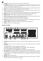
1.- M
ONITOR (1 W, 8 Ω)
: output for connection of a low impedance loudspeaker 8 Ω to monitor the output.
2.-
PRIORITY
: when closing the contacts of these two terminals, the order of priority of the inputs changes.
The order of priority without closing the contacts is as follows:
TEL.PAGING > MIC 1 >
M-46
Microphone > MIC 2, MIC 3, LINE 4, LINE 5, MP3 Module.
The order of priority when closing the contacts is as follows:
MIC 1 > TEL.PAGING >
M-46
Microphone > MIC 2, MIC 3, LINE 4, LINE 5, MP3 Module.
3.-
TEL. PAGING
: telephone input connection terminals. These allow you to connect to a telephone
switchboard to prioritize paging over other inputs. Make the connection between terminals T and G.
Consult the characteristics of the control unit to adjust to the input level of the amplifier.
4.-
FM ANT
: FM antenna input.
5.-
REC OUT
: balanced or unbalanced line output. Signal output for recording, mixer, power stage, etc.,
screw terminal connections. general speaker output. For connection of low impedance 4 Ω and high
impedance 100 or 70 V lines, connect the speaker line between the COM terminal and the desired
impedance or V line.
6.-
OUTPUT
: loudspeaker general output. For the connection of low impedance loudspeakers 4 Ω and in
high impedance lines of 100 or 70 V, connect the loudspeaker line between the COM terminal and the
impedance or line in V required.
7.-
GND LIFT
: this switch is normally in the GND position. If there are grounding noises, switch to the LIFT
position, disconnecting the device from the ground.
8.- AC power socket.
9.-
ZONE
: microswitches to select in which zone or zones the TEL PAGING input will be heard.
10.-
VOLUME
: a rotating dial that regulates the volume of the TEL PAGING input.
11.-
CH 4, CH 5
: line level inputs. Allow for the connection of audio sources, 2 x RCA connectors.


