Folger Tech FT-5 Owner'S Manual Download Page 30


 FT-5 User Manual Page 29 

6.


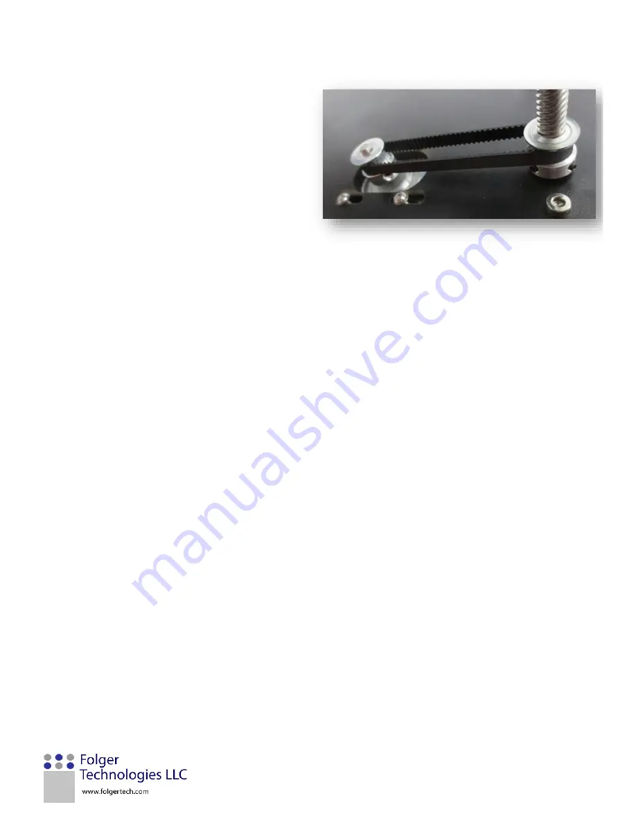
Insert one of the 20T 5mm bore pulleys onto 
the stepper motor located on the base plate. 
Loosen the four stepper motor screws and 
position the belt so it is in both of the toothed 
groves on both pulleys. Ensure the belt is strait 
and tighten the screws on the stepper motor.  


7.


Repeat steps 3-6 on the other threaded rod. 


Summary of Contents for FT-5

Page 1: ......

Page 2: ...Assemble the Top Plate 24 4 Install Base and Top Plate 25 5 Assemble Bed Plate 26 6 Mounting Bed 27 7 Assemble Y Gantry Rails 30 8 Gantry Assembly 33 9 Hotend 37 10 Endstops and Belts 43 11 Mounting...

Page 3: ...a 77 Printing Settings 81 Printing Setting Definitions 81 Generating G code using Cura 87 Step by Step Process 87 3 Printing from an SD Card 89 Step by step Process 89 Printer Operation 90 Changing Fi...

Page 4: ...y wipe them down with a damp rag but do not soak them It will cause the parts to swell and or break CONTACT FOLGER TECH We understand that manual only covers the basics of your Folger Tech printer so...

Page 5: ...oot 46 2 Green Female Block 13 2 T8 Leadscrew Nut 47 1 4pin XH Both Ends 14 5 20T 5mm Bore Pulley 48 1 CH2 Springs Connectors 15 2 20T 8mm Bore Pulley 49 2 Green Male Blocks 16 2 GT2 188 Belt Loop 50...

Page 6: ...ylon Spacers AH 8 M4 Set Screw Q 8 M4 set screw AI 2 M3 Set Screws R 28 M4 T nut AJ 2 Fuse FOLGER TECH FT 5 LASER CUT PARTS Item ID Total Supplied Description Item ID Total Supplied Description FT1 13...

Page 7: ...FT 5 User Manual Page 6 1 700mm 2020 Beam 4 500mm 2040 Beam 2 500mm 2020 Beam 3 460mm 2020 Beam 8 5 0kg cm Motor 18 GT2 Belt 17 Idler Pulley 14 20T 5mm Bore Pulley 15 20T 8mm Bore Pulley...

Page 8: ...188mm GT2 Belt Pulley 5 Slide Rail 6 500mm M8 PCR 7 500mm M8 Leadscrew 21 Fan 24 3D Hotend 20 Heat Sink Fin 9 Upper Block 19 MK9 19 Drive Gear with MK9 23 M6 PTFE Threaded Tube 35 2004 LCD Screen 36...

Page 9: ...FT 5 User Manual Page 8 25 300 x 300 Aluminum Heated Bed 28 AC Power Cable 29 USB Port 30 Power Outlet 27 Power Supply...

Page 10: ...FT 5 User Manual Page 9 FT23 FT19 FT22 FT17 FT18 FT15 FT16...

Page 11: ...FT 5 User Manual Page 10 FT14 FT12 FT6 FT11 FT25 FT5 FT10 FT27 FT13 FT4 FT3 FT9 FT7 FT8 FT26 FT1 FT2...

Page 12: ...FT 5 User Manual Page 11 FT21 FT20 11 LM8FLUU 10 KFL8 13 T8 Leadscrew Nut 12 Rubber Feet 9 SHF8 31 Cable Chain 33 Cable Chain End Male 32 Cable Chain End Female...

Page 13: ...DEFINITIONS The figure below shows the features of the Folger Tech FT 5 3D printer You can reference this graphic for clarification of printer parts mentioned in this manual Hotbed Filament Spool Hot...

Page 14: ...s the filament as it gets pushed through the Bowden Tube by the Extruder It is comprised of the following parts Gantry The gantry moves in the Y direction and has the Extruder mounted to it Power Supp...

Page 15: ...for functionality to return Info Screen The info screen is the home screen display for the LCD screen Main Menu Press in on the control knob from the info screen to navigate to the Main Menu Watch Ret...

Page 16: ...e two common features that will be used on this screen are Auto Home Zeros the machine and returns the effector to the home position Preheat PLA Sets the hot end temperature to 200 C and the bed to 70...

Page 17: ...d to complete your 3D printer Phase Assembly Description Page 1 Assemble the Frame 16 2 Assemble the Base Plate 20 3 Assemble the Top Plate 22 4 Install Base and Top Plate 24 5 Assemble Bed Plate 25 6...

Page 18: ...eam 3 4 460mm 2020 Beam 12 4 Rubber Feet N 4 L Bracket FT25 1 LCD Panel FT1 13 Corner 4 Bolt FT2 8 Corner 5 Bolt Z 96 M5x10mm Screw Y 96 M5 T nut AH 8 M4 Set Screw 1 Place the 500mm 2040 beam down on...

Page 19: ...e and finish them off with a M5 T nut NOTE Only 13 FT1 will be used See step 7 there are none used on the bottom rear of the printer 4 Place the corner so that the bottom two T nuts slide into the upp...

Page 20: ...steps 3 and 4 for the other side of the corner Note this one will have the screws going through the opposite way 6 Insert the 700m 2020 beam down into all 4 M5 T nuts Tighten down the T nuts and make...

Page 21: ...as steps 3 6 attach three more corners on the frame NOTE The opposite side of the LCD Panel and left corner the BACK has no corner pieces on it and will be covered with the back electronics box panel...

Page 22: ...be 170mm apart Attach a 460mm 2020 beam to the middle brace 11 Repeat steps 9 and 10 on the remaining 7 middle braces Note that the front and back are 500mm AL beams and the sides are 460mm 2020 beam...

Page 23: ...C 8 M3 Washer F 8 M3x10mm Screw I 4 M3x20mm Screw S 12 M4 Nylock V 4 M4x16mm Screw W 8 M4x20mm Screw 1 Insert the stepper motor through one of the two stepper mounting holes on the Bottom Panel the to...

Page 24: ...ne KFL8 and place them on the underside of the Bottom Panel Secure the two SHF8 in place using two M4x20mm screws and M4 Nylocks The KFL8 is secured in place using two M4x16mm screws and two M4 Nylock...

Page 25: ...M3x10mm screws and two M3 washers The motor cable connector should face towards the right Note Position the motor all the way to the center of the panel This will be helpful when adding the belts in a...

Page 26: ...p the machine with the top on the table Insert the left Upper Panel FT18 under the center of the frame All of the outside T nuts should line up and lock in place 2 Repeat step 2 on right Upper Panel F...

Page 27: ...11 4 LM8FLUU 13 2 T8 Leadscrew Nut H 24 M3x16mm Screw A 24 M3 Nylock 1 Insert two of the LM8FLUU into the outer holes Secure them in place four M3x 16mm screw and four M3 Nylock Insert T8 Leadscrew n...

Page 28: ...ey 14 2 20T 5mm Bore Pulley 16 2 GT2 188 Belt Loop 1 Insert the four M8 PCR through the SHF8 on the bottom of the frame and through the LM8FLUU on the bed 2 Slide the M8 PCR all the way through until...

Page 29: ...e frame You may need to loosen the set screws on the KFL8 Take one of the 20T 8mm bore pulleys and one of the GT2 belts and insert them on the threaded rod 4 Thread the threaded rod through the bed pl...

Page 30: ...he stepper motor located on the base plate Loosen the four stepper motor screws and position the belt so it is in both of the toothed groves on both pulleys Ensure the belt is strait and tighten the s...

Page 31: ...y Description 5 3 Slider Rail 2 2 460mm 2020 Beam 39 1 Kapton Tape E 32 M3x8mm Screw B 24 M3 T nut D 2 M3 Square nut H 2 M3x16mm Screw Z 4 M5x10mm Screw Y 4 M5 T nut FT5 2 Y Belt FT10 1 Idler 7 Bolt F...

Page 32: ...he M3 screws in 4 Repeat step 3 on the other 2020 beam The remaining slider rail will be used at a later step 5 Line up the two rails and align the sliders with each other Use some kapton tape to lock...

Page 33: ...M3x16mm screw This will lock the two parts together 7 Insert two M5x10mm screws into each one and finish them off with two M5 T nuts 8 Position the two rails parallel to each other Set the two laser c...

Page 34: ...500mm 2020 Beam 1 Slider Rail Phase 7 F 5 M3x10mm Screw H 2 M3x16mm Screw B 1 M3 T nut A 1 M3 Nylock Z 4 M5x10mm Screw Y 4 M5 T nut FT8 1 Motor Right Middle FT4 1 Idler 2 Bolt 1 Lay the 500mm rail fl...

Page 35: ...countersunk side of the hole should be on the same side as the T nuts 4 Take the motor right middle and insert two M5x10mm screws through and finish them off with two M5 T nuts The lettering should be...

Page 36: ...ddle and finish them off with two M3 Nylock 7 Slide the 5mm bore pulley onto the shaft of the stepper motor Secure it in place by tightening the two set screws on the pulley 8 Place the idler 2 bolt o...

Page 37: ...o the idler 2 bolt Secure the slider rail in place Note If the screws were not installed on the slider rail refer to phase 7 step 1 for details 10 Put the stepper motor onto the 2020 beam and butt it...

Page 38: ...Cable Chain Ends 33 1 Male Cable Chain Ends A 10 M3 Nylock G 6 M3x12mm Screw H 4 M3x16mm Screw K 6 M3x40mm Screw L 4 M3x45mm Screw FT9 1 Motor Right Top FT11 1 Extruder Front Plate FT12 1 Extruder Ba...

Page 39: ...the MK9 One is located behind the lever by the spring 3 Lay the Al upper block on the stepper motor so that the M6 threaded hole is on the left 4 Lay the heat sink fin on top of the Al upper block Us...

Page 40: ...hain is centered and that the four mounting holes are not covered 6 Take four M3x16mm screws and insert them through the four holes on the FT13 Then through four holes of the FT27 Make sure the tabs p...

Page 41: ...r 9 Slide the hotend assembly over the tabs of the top FT27 Lock this in place using four M3x45mm screws and four M3 Nylock There are two screws on top and two on bottom 10 Take FT9 and lay it face do...

Page 42: ...female cable mount over the two holes Secure it in place using two M3x12mm screw and two M3 Nylock 12 Remove two of the screws from the back of the stepper motor 13 Place FT9 over the back of the step...

Page 43: ...the slides to get it to fit 15 You may need to adjust the gap between each rail Loosen the two M5 screws on either the X motor mount or the idler 16 When the two 2020 beams are seated on all of the T...

Page 44: ...dler Pulley 31 1 meter Cable Chain A 7 M3 Nylock G 5 M3x12mm Screw I 3 M3x20mm Screw Z 9 M5x10 Y 9 M5 T nut AC 6 Zip Ties 18 4 meter GT2 Belt FT3 1 Idler 4 Bolts Right FT6 1 Y endstop Mount FT26 1 Idl...

Page 45: ...0 Take a 5mm bore pulley and place it onto the shaft of one of the y axis stepper motors Lock it in place using the two set screws Repeat this for the other y axis stepper motor 21 Take the cable chai...

Page 46: ...e end of the other section about 19 links note using more than 19 links will cause the cables to be to short of cable chain onto the male cable mount Secure the other end of the cable chain onto the f...

Page 47: ...d endstop mount and an endstop and secure it in place using two M3x20mm screws and two M3 Nylocks 27 Position the endstop onto the back right M8 PCR Insert a M3x20mm screw through the end and finish i...

Page 48: ...und the Y stepper motor pulley 31 Loop the end of the belt through the other end of the Y Belt Pull the belt tight and use a zip tie to secure it in place Trim any excess belt 32 Loosen the two screws...

Page 49: ...e it with a zip tie 35 Loop around the stepper motor pulley 36 Loop around the idler pulley Finish it off by looping through the other end of the extruder back plate Use a zip tie to secure it in plac...

Page 50: ...crew H 16 M3x16mm Screw D 10 M3 Square Nut P 4 Nylon Spacer Z 2 M5x10mm Screw Y 2 M5 T nut 43 1 150mm M5 Threaded Rod X 2 M5 Nylock AD 1 Printed Estop Button U 4 M4x10mm Screw FT19 1 Electronics Box M...

Page 51: ...p the slots with the tabs Slide a M3 square nut into the slot and screw a M3x16mm screw in It should look like the picture to the right with the base at the bottom and electronics facing the rear of t...

Page 52: ...op and secure it in place using four M3x16mm screws and four M3 square nuts 9 Take the LCD screen and remove the knob from the panel Place the orange stop button through FT25 and then place the LCD sc...

Page 53: ...8 and PVC Pipe and sandwich the PVC pipe between the two pieces Insert the M5 threaded rod through and secure the whole thing in place using two M5 Nylocks 11 Mount the spool holder on the back right...

Page 54: ...Aluminum Bed Plate Old Style White Aluminum Heated Bed New Style 45 1 Thermistor 56 1 14 AWG Wire 63 1 Braided Cover 39 1 Kapton Tape O 6 Bed spring I 6 M3x30mm Screw M 6 M3 thumb Screw You may want...

Page 55: ...e heat shrink 3 Secure the thermistor down using a few pieces of kapton tape Note Add some kapton or electrical tape to the other side of the solder joints for the two power wires This will help preve...

Page 56: ...FT 5 User Manual Page 55 5 Secure each of the six hole locations with a M3x30mm screw bed spring and a M3 thumb screw...

Page 57: ...s 300mm from the 4 pin board connector Strip inch off each wire 4 Combine the following two wires together Insert them into the 4 pin green connector with the screws facing up As from looking from the...

Page 58: ...ake 4 pin connector and the 2 meter endstop cable red green and black 24 awg wire insert the 4 pin connector into the x axis limit switch Looking at the bottom of the limit switch insert the four wire...

Page 59: ...Prepare the hotend bundle by removing the connector from the board side of the extruder motor cable This will help with feeding the bundle through the cable chain Using electrical or kapton tape tape...

Page 60: ...ng order white white red black The orientation of the thermistor is not important but the fan wires are Make sure to feed on heat shrink before soldering and then cover the solder with heat shrink 14...

Page 61: ...r might vary from the one pictured 16 Remove the two top screws on the hotend and insert two small cable clamps one on each The left one should have all the wiring in it and the right one should be em...

Page 62: ...stop Make sure to tape and label each bundle Take the X axis stepper cable X axis endstop cable hotend bundle and the extruder stepper cable and tape the ends of them together 20 Feed the bundle made...

Page 63: ...r end Take a motor cable without board connector and combine the similar colored wires 24 Take the green four terminal connectors insert the wires in the following order Green Gray Yellow and Red Take...

Page 64: ...14 awg wires too Solder or use up spade connectors If you have them the green wire to the top connector pin 1 of the power outlet The red wire goes on the pin 2 The two inch black jumper goes from pi...

Page 65: ...er Insert the wires to the right of the screw That way when the screw is tightened down it pulls the wire in tight 30 Take the red and black 14 awg wires and cut two 5 inch lengths of each Strip inch...

Page 66: ...Connecting this wrong will burn out the board 32 Cut and strip the two wires from the electrical box fan Strip the two wires from the hotend fan Insert these wires into the remaining positive and nega...

Page 67: ...iddle is the heated bed and the bottom is the hotend thermistor 36 Insert the heatbed wires and the hotend heater wires into the board The color orientation of these two do not matter 37 Add the heats...

Page 68: ...on successfully assembling your Folger Tech FT 5 3D Printer Kit Now that it is built it s time to verify that all the components are working properly This will require a computer and the USB cable th...

Page 69: ...ant that you follow these steps and do not power up the printer before being instructed to do so 1 The power coming into the board should be Black Red Black Red for the 2 big green plugs on the MKS bo...

Page 70: ...rs should be in the following order X Min None Y Min None Z Min None 4 All of the stepper drivers should be pointing to the left trim pot facing away from the power input plugs 5 Verify that the fuse...

Page 71: ...r and allows the user to send individual g code files to the printer http www pronterface com Cura Cura is the slicing software that turns the digital object which is the stl file 3D model into the g...

Page 72: ...ted to the computer and it has recognized Arduino it s time to open the Pronterface software Open the Pronterface folder on the SD card and select the Pronterface icon shown in the image below We sugg...

Page 73: ...ded rods with your hands so the Z endstop is not engaged In the bottom right of the screen in Pronterface type in m119 and click send This code will tell the printer to send back the status of the end...

Page 74: ...the motors are wired correctly click on the home button on Pronterface This will tell the gantry to move towards the home position Note that at any time durring this step be ready to turn off the pri...

Page 75: ...all machines This value can be fine tuned to maximize z height Open Marlin ino and click on the Configuration h tab Scroll down until you find the Travel limits after homing then define Z_MAX_POS Thi...

Page 76: ...ch the graph to make sure the temperature of the hot end is heating up and holds steady around 230 C If the bed temp is rising then they are plugged in backwards Set the bed temp to 100 and click the...

Page 77: ...he hot end at 230 C click on the Extrude button on Pronterface The extruder will not run if the hot end is under 170 C Now the drive gear should turn in a clockwise direction Turn off the hot end by c...

Page 78: ...Tech recommends using Cura for slicing and G code generation other slicing software can be used The printer parameters detailed below are a recommended for optimum performance of a Folger Tech printer...

Page 79: ...FT 5 User Manual Page 78 4 Click Next on the Configuration Wizard...

Page 80: ...FT 5 User Manual Page 79 5 Under Select your machine choose Other Ex RepRap MakerBot Witbox Then click Next 6 Under Other machine information select Custom and click Next...

Page 81: ...FT 5 User Manual Page 80 Input the following values into the RepRap custom settings Machine height was calculated in a previous section...

Page 82: ...to the different settings that may need to be changed and which settings should remain constant depending on your desired results PRINTING SETTING DEFINITIONS Basic Settings The parameters that are fr...

Page 83: ...lue must be a multiple of the layer height For example a part with a layer height of 0 2 mm will have 3 solid bottom and top layers when the input is 0 6 mm for this parameter Fill Density This descri...

Page 84: ...equirement including overhangs that are over another section of the part Clicking on the button will bring up the Expert config window where additional features can be edited Platform adhesion type Th...

Page 85: ...This value can be adjusted to optimize the quality of the print A typical value is between 90 100 for your FT 5 printer If excessive plastic is being extruded reduce this value by 5 Advanced Settings...

Page 86: ...ssed Travel speed mm s The speed at which the hot end moves when it s not extruding filament Bottom layer speed mm s The speed at which the hot end moves when printing the first layer This value is ty...

Page 87: ...interprets all dimensions in millimeters If the model was made using inches it will appear very small in the Cura window Simply select the part and uniformly scale it by 25 4 to restore the part to it...

Page 88: ...ntrol the printer motors and heater Individual objects may require changing some of the parameters discussed in the previous sections to obtain the desired quality and speed STEP BY STEP PROCESS 1 Ver...

Page 89: ...ture is required Reference the Printing Settings Definitions section for help manipulating the part 4 Verify and adjust any of the Basic and Advanced printing settings See the Printer Settings Definit...

Page 90: ...e must be restarted to recognize the card 3 Press the control knob once to reach the Main Menu 4 Scroll down to Print from SD and press the control knob again to select this function 5 Use the control...

Page 91: ...ing temperature 210 C for PLA and 230 C for ABS 2 Push up on the extruder lever and slightly push in on the filament until it comes out of the tip of the nozzle The figure below shows the extruder lev...

Page 92: ...needs to be replaced 2 Apply the new Scotch Blue painters tape to the bed to replace the tape that was removed 3 Gently press down on the new tape to smooth out the edges Ensure there are no bubbles i...

Page 93: ...rmistor is tight if the thermistor comes loose and falls out the hot end will heat uncontrollably TROUBLESHOOTING The table below shows some of the most common problems experienced with 3D printer use...

Reviews: