


Locking
assembly:
Action:
• 84 59 12
• 84 59 13
• 84 59 14
• 84 59 17
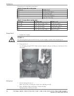
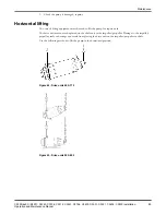
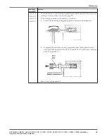
1. Loosen the screws on the locking assembly evenly and in sequence. See
tightening or loosening locking assembly bolts
(page 99).
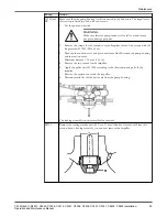
If the locking assembly is still locked, do as follows:
a.
Loosen the inner ring by tapping it lightly, as shown in the illustration.
b. If tapping did not loosen the ring, replace the three "light-colored" screws
with three M10 draw-bolts (for 84 59 12 and 84 59 13) or M12 draw-bolts (for
84 59 14 and 84 59 17).
M10
M12
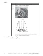
2. Remove the locking assembly.
Maintenance
C3300/6x5, C/R3231, C3240, C3306, C3312, C3351, C3356, C3400, C3501, C3531, C3602, C3800 Installation,
Operation and Maintenance Manual
95


