background image

Type of  service

Purpose

Interval

Major overhaul

To secure a long operating

lifetime for the product. It

includes replacement of  key

components and the

measures taken during an

inspection.

24,000 hours or 6 years, whichever comes first.

Applies to normal applications and operating

conditions at media (liquid) temperatures

< 40°C (104°F).

NOTICE:
Shorter intervals may be required when the operating conditions are extreme, for example with very
abrasive or corrosive applications or when the liquid temperatures exceed 40°C (104°F).

Inspection

CAUTION:
The inside may be pressurized. Be careful when opening the inspection covers.

Regular inspection and service of  the pump ensures more reliable operation.

Do the following to service the pump:

Part to service

Action

Pump casing

Check the entire pump and the cables for external mechanical damage.

Cable

1. If  the outer jacket is damaged, replace the cable.
2. Check that the cables do not have any sharp bends and are not pinched.
3. Check that the leads and cable entry screws are correctly connected and

tightened to the correct torque.

Lifting handle

Check the lifting handle for corrosion or other damage.

Junction box

1. General:

Check that it is clean and dry.
If  it is wet:
a.

Check the cable entry.

b. Replace the O-rings. (New O-rings should be fitted to all O-ring seal

joints opened during inspection.)

2. Terminal board: Check that the connections are properly tightened.

Junction box

insulation, drive units

up to 1.1 kV

Check the condition and function. See 

Check the junction box insulation, up to 1.1

kV drives

 (page 84).

Junction box

insulation, drive units

1.2 - 6.6 kV

Check the condition and function. See 

Check the junction box insulation, 1.2-6.6

kV drives

 (page 84).

Stator housing

1. Check that it is clean and dry:

• If  there is oil in the stator housing, drain and clean. After one week of

operation, check again. If  there is still oil in the stator housing, change
the seals.

• If  there is water in the stator housing and there was water in the oil,

change the seals immediately.

• If  there is water in the stator housing, but there was no water in the oil,

check all other connections.

2. Replace the O-rings.

Maintenance

82

C3300/6x5, C/R3231, C3240, C3306, C3312, C3351, C3356, C3400, C3501, C3531, C3602, C3800 Installation,

Operation and Maintenance Manual

Summary of Contents for C/R3231

Page 1: ...reted as a reference by the Company to ITT in the Company s current business activities Any use or reference to ITT by you is strictly prohibited In no event will we be liable for any incidental indirect consequential punitive or special damages of any kind or any other damages whatsoever including without limitation those resulting from loss of profit loss of contracts loss of reputation goodwill...

Page 2: ...End of Disclaimer text ...

Page 3: ...Water Wastewater Installation Operation and Maintenance Manual C3300 6x5 C R3231 C3240 C3306 C3312 C3351 C3356 C3400 C3501 C3531 C3602 C3800 ...
Page 4: ......

Page 5: ...Product Description 20 Pump Design 20 Intended Use 20 Approvals 20 Spare parts 21 Drive units 21 The monitoring equipment 24 Monitoring alternatives MAS and CAS overviews 26 Sensors 27 Stator temperature monitoring methods 31 Pt100 resistance 32 Pump memory 33 The cooling system 33 Direct cooling 33 Integrated cooling 33 External Cooling 35 Fittings needed to drain cooling jacket 38 Seal Flushing ...

Page 6: ...box insulation 1 2 6 6 kV drives 84 Check the temperature sensors 84 Check the leakage sensors 85 Empty the coolant integrated cooling 85 Empty the coolant external cooling 86 Oil change 87 Empty the oil 88 Fill with oil 88 Horizontal lifting 89 Replace the wear parts 90 Replace the pump housing wear ring 90 Replace the impeller wear ring 91 Replace the impeller 92 Remove the impeller 92 Remove th...

Page 7: ... Medium voltage 126 C3501 Motor rating and performance 50 Hz 127 Low voltage 127 Medium voltage 128 C3531 Motor rating and performance 50 Hz 129 Low voltage 129 Medium voltage 131 C3602 Motor rating and performance 50 Hz 134 Low voltage 134 Medium voltage 135 C3800 Motor rating and performance 50 Hz 137 Low voltage 137 Medium voltage 138 C3231 Motor rating and performance 60 Hz 139 Low voltage 139...

Page 8: ... Medium voltage 151 C3501 Motor rating and performance 60 Hz 153 Low voltage 153 Medium voltage 154 C3531 Motor rating and performance 60 Hz 156 Low voltage 156 Medium voltage 158 C3602 Motor rating and performance 60 Hz 160 Low voltage 160 Medium voltage 161 C3800 Motor rating and performance 60 Hz 163 Low voltage 163 Medium voltage 164 Table of Contents 4 C3300 6x5 C R3231 C3240 C3306 C3312 C335...

Page 9: ...maged or are missing 3 If applicable unfasten the product by removing any screws bolts or straps For your personal safety be careful when you handle nails and straps 4 Contact your sales representative if anything is out of order Product warranty Coverage ITT undertakes to remedy faults in products from ITT under these conditions The faults are due to defects in design materials or workmanship The...

Page 10: ...regarding the intended use of the equipment please contact an ITT representative before proceeding This manual clearly identify accepted methods for disassembling units These methods must be adhered to Trapped liquid can rapidly expand and result in a violent explosion and injury Never apply heat to impellers propellers or their retaining devices to aid in their removal Do not change the service a...

Page 11: ...rds Always bear in mind the risk of drowning electrical accidents and burn injuries Safety equipment Use safety equipment according to the company regulations Use this safety equipment within the work area Helmet Safety goggles preferably with side shields Protective shoes Protective gloves Gas mask Hearing protection First aid kit Safety devices NOTICE Never operate a unit unless safety devices a...

Page 12: ...or Ex approved products must conform to international and national standards for example IEC EN 60079 17 ITT disclaims all responsibility for work done by untrained and unauthorized personnel Product and product handling requirements These are the product and product handling requirements for Ex approved products in potentially explosive atmospheres Only use the product in accordance with the appr...

Page 13: ...itoring equipment For additional safety use condition monitoring devices Condition monitoring devices include but are not limited to the following Level indicators Temperature detectors Environmental safety The work area Always keep the station clean to avoid and or discover emissions Waste and emissions regulations Observe these safety regulations regarding waste and emissions Appropriately dispo...

Page 14: ... Make sure that the product is securely fastened during transportation and cannot roll or fall over Horizontal position Figure 1 Horizontal position for transport The impeller must be locked during transportation if the pump is transported in the horizontal position Vertical position Transportation and Storage 10 C3300 6x5 C R3231 C3240 C3306 C3312 C3351 C3356 C3400 C3501 C3531 C3602 C3800 Install...

Page 15: ...e floor must be sufficient to lift the pump The lifting equipment must be able to hoist the pump straight up and down preferably without the need for resetting the lifting hook The lifting equipment must be securely anchored and in good condition The lifting equipment must support weight of the entire assembly and must only be used by authorized personnel Two sets of lifting equipment must be used...

Page 16: ...ifting drive unit only or complete pump C3231 C3356 with 705 775 drive units Placement for lifting complete pump C3400 C3602 with 705 775 drive units Figure 4 Drive units 705 775 When lifting only the drive unit for C3400 C3602 pumps the lifting cover must be turned 180 Transportation and Storage 12 C3300 6x5 C R3231 C3240 C3306 C3312 C3351 C3356 C3400 C3501 C3531 C3602 C3800 Installation Operatio...

Page 17: ...ransport pallet 1 Fasten a suitable lifting strap sling to the lifting eye on the top of the drive unit See Lifting page 11 2 Cut the transportation strap 3 Lift up the pump using proper lifting equipment 4 Place the pump upright on a rigid horizontal surface so that it cannot fall over Transportation and Storage C3300 6x5 C R3231 C3240 C3306 C3312 C3351 C3356 C3400 C3501 C3531 C3602 C3800 Install...

Page 18: ...quipment 1 Fasten a suitable lifting sling strap to the lifting eye on the top of the drive unit See Lifting page 11 2 Raise the pump approximately halfway to its upright position The pump is still be attached to the transport pallet 3 Slide a pallet or similar object under the inlet section This will minimize the jolt which may occur later in the lifting when the pump is almost fully upright Tran...

Page 19: ...mp until it is in an upright position The pump may jolt or sway near the end of the lifting operation WARNING Keep a safe distance while the unit is moving 5 Remove the straps holding the pump to the transport pallet Transportation and Storage C3300 6x5 C R3231 C3240 C3306 C3312 C3351 C3356 C3400 C3501 C3531 C3602 C3800 Installation Operation and Maintenance Manual 15 ...
Page 20: ...e the support pallet 8 Place the pump upright on a rigid horizontal surface so that it cannot fall over Transportation and Storage 16 C3300 6x5 C R3231 C3240 C3306 C3312 C3351 C3356 C3400 C3501 C3531 C3602 C3800 Installation Operation and Maintenance Manual ...
Page 21: ...p to the transport pallet 4 Lift up the pump 5 Place the pump upright on a rigid horizontal surface so that it cannot fall over Install the guide claw 3800 only The guide claw is delivered detached from the pump 1 Clean the contact surfaces shown with arrows in the figure below Transportation and Storage C3300 6x5 C R3231 C3240 C3306 C3312 C3351 C3356 C3400 C3501 C3531 C3602 C3800 Installation Ope...

Page 22: ...ed out of the liquid into a surrounding temperature below freezing Follow these guidelines to avoid freezing damage When Guideline Before storage The pump must be allowed to run for a short time after raising it to discharge remaining pumped liquid This does not apply to propeller pumps The discharge opening must be covered in a suitable way or placed facing down so that any still remaining pumped...

Page 23: ...ther month to prevent the seals from sticking together Reinstall the locking device If the pump will be transported in the horizontal position then the impeller propeller must be locked during transport with the locking device 1 Reinstall the locking device 2 Clamp the locking device into position by turning and locking it by hand as tightly as possible 3 Tighten a further 1 8 to 1 3 of a turn acc...

Page 24: ...t explosion proof products have For more information please contact your ITT representative In addition to the data plate explosion proof products also have either an EN or a FM approval plate EN European Norm EN approvals ATEX Directive EN 50014 EN50018 EN 1127 1 II 2 G EEx dII T4 T3 6x5 II 2 G EEx dIIB T4 T3 7x5 II 2 G EEx dII T3 8x5 II 2 G EEx dII T4 25 C T3 9x5 T4 on option 1 2 3 4 5 6 7 8 9 1...

Page 25: ...The following applies when servicing or repairing the pump Modifications to the unit or installation should only be carried out after consulting with ITT Original spare parts and accessories authorized by ITT are essential for compliance The use of other parts can invalidate any claims for warranty or compensation For more information contact your ITT representative Drive units C3231 Voltage range...

Page 26: ...12 Voltage range Standard drive units Explosion proof drive units Maximum number of starts per hour Up to 1 1 kV 705 715 15 735 745 15 765 775 15 835 845 15 865 875 15 885 895 8 1 2 6 6 kV 862 872 15 882 892 8 C3351 Voltage range Standard drive units Explosion proof drive units Maximum number of starts per hour Up to 1 1 kV 905 915 6 935 945 6 965 975 6 1 2 6 6 kV 950 960 6 985 995 6 C3356 Voltage...

Page 27: ...1 1 kV 705 715 15 735 745 15 765 775 15 805 815 15 835 845 15 865 875 15 885 895 8 1 2 6 6 kV 862 872 15 882 892 8 C3531 Voltage range Standard drive units Explosion proof drive units Maximum number of starts per hour Up to 1 1 kV 705 715 15 735 745 15 765 775 15 805 815 15 835 845 15 865 875 15 885 895 8 905 915 8 935 945 8 965 975 8 1 2 6 6 kV 862 872 15 882 892 8 950 960 8 985 995 8 Product Des...

Page 28: ...ncludes a pump memory module storing identity data of the pump The parameters tracked are chosen by the customer and may include the following Temperature main and support bearings stator winding Vibration Leakage in the stator housing the junction box and water in the oil chamber Power monitoring For more information see the Installation and User Manual for MAS 711 monitoring systems Pump current...

Page 29: ...ormers Optional For more information on the stator temperature monitoring see Stator temperature monitoring methods page 31 Sensors drive units 1 2 6 6 kV The drive units in this voltage range are shown in Drive units page 21 Table 2 Sensors for pumps using 1 2 6 6 kV drive units Description Sensor Signal Cable Number of Leads Required Standard or Optional Vibration VIS 10 24 Optional Leakage in t...

Page 30: ...a plate see The data plates page 43 MAS system MAS is the standard monitoring equipment Pumps with the standard MAS equipment with a 12 lead auxiliary cable are mounted with the following items Thermal switches for stator temperature monitoring 3 in series or PTC thermistors Leakage sensor in the stator housing Leakage sensor in the junction box Analogue temperature sensor Pt100 for main bearing t...

Page 31: ... longer available as a spare part but if necessary CAS may be replaced by the MAS 711 together with the MRM 01 relay For more information see CAS or MAS 711 MRM 01 sensor connections page 55 Sensors 6X5 drive units 6 4 7 8 2 1 3 5 WS000628A 1 Vibration VIS 10 2 Leakage in the junction box FLS Float Switch Leakage Sensor 3 Stator winding temperature 4 Main bearing temperature Pt100 analogue tempera...

Page 32: ...erature Pt100 analogue temperature sensor 5 Leakage in the stator housing FLS 6 Water in oil standard drive units only CLS Capacitive Leakage Sensor 7 Support bearing temperature Pt100 analogue temperature sensor 8 Pump memory Product Description 28 C3300 6x5 C R3231 C3240 C3306 C3312 C3351 C3356 C3400 C3501 C3531 C3602 C3800 Installation Operation and Maintenance Manual ...

Page 33: ... 7 Support bearing temperature Pt100 analogue temperature sensor 8 Pump memory Temperature sensors Table 3 Thermal switch Description Measured value Fault values The thermal switch is a normally closed contact 0 3 ohm unless the wires are very long An infinite value open circuit indicates either high temperature or a fault a wire is broken or there is a bad contact in a connector Product Descripti...

Page 34: ... 70 ohm approx indicates Short circuit For information on the various configurations of switches thermistors and sensors used to monitor stator winding temperature see Stator temperature monitoring methods page 31 FLS Table 6 Float switch sensor FLS Description Measured value Fault values The float switches are leakage sensors located in the lower part of the stator housing and in the junction box...

Page 35: ...the voltage range for each drive unit Up to 1 1 kV drive units Table 10 Stator temperature monitoring configuration up to 1 1 kV Standard Optional Monitoring Configuration Description Standard This method uses the following configuration Three thermal switches connected in series are incorporated in the coil ends of the stator winding The switches are normally closed and open at 140 C 285 F One Pt...

Page 36: ... 126 69 102 139 26 135 151 70 4 101 56 37 114 38 70 127 07 103 139 64 136 152 08 5 101 95 38 114 77 71 127 45 104 140 02 137 152 45 6 102 34 39 115 15 72 127 84 105 140 39 138 152 83 7 102 73 40 115 54 73 128 22 106 140 77 139 153 20 8 103 12 41 115 93 74 128 60 107 141 15 140 153 58 9 103 51 42 116 31 75 128 98 108 141 53 141 153 95 10 103 90 43 116 70 76 129 37 109 141 91 142 154 32 11 104 29 44...

Page 37: ... external cooling system For more information regarding the versions please contact your ITT representative NOTICE Always operate the pump with the drive unit completely submerged in the pumped liquid if the pump is delivered without the integral drive unit cooling jacket When emptying the sump the lowest liquid level must not be lower than the top of the pump housing Contact your local ITT repres...

Page 38: ...t needed for integrated cooling Circulation through the cooling jacket is provided by back vanes on the impeller Ports and fittings With integrated cooling the cooling jacket is equipped with the following ports Port Quantity Description Inlet pipes 2 Diametrically opposed one at bottom and one approximately 2 3 up Not external ports no inlet connection required during pump installation Product De...

Page 39: ...ng the motor The cooling water circuit may be open or closed In both cases it is completely isolated from the pumped media The figure below shows the principle of the external cooling system Applications where external cooling might be used include the following If the temperature of the pumped media exceeds 40 When extreme amounts of concentrated sewage where grease or fats are present is combine...

Page 40: ...y should be arranged as shown in the figure below M M F000156B 1 2 3 4 5 6 7 1 Cooling water supply 2 Expansion tank 3 Flow meter 4 Circulation pump 5 Coolant in 6 Coolant out 7 Heat exchanger Item Notes Cooling water supply Incoming supply should be equipped with a vacuum valve It should also be separated from the cooling circuit with a non return check valve Expansion tank Equipped with a level ...

Page 41: ...et can be drained before service work See Fittings needed to drain cooling jacket page 38 For P and S installations two 1 inch inner diameter reinforced water hoses are needed To avoid movement in the sump they should be fixed with cable ties to the cables For T and Z installation pipes should be used instead of hoses to minimize the risk of accidental leakage Flexible connections for example rein...

Page 42: ...uired flow of coolant is maintained during pump operation The flow meter should have an electric output that can be wired into the pump power supply circuit in such a way that the pump is stopped if the flow of coolant is interrupted Fittings needed to drain cooling jacket This section describes the fittings needed to drain the cooling jacket It is applicable to both integrated cooling and externa...

Page 43: ... Shutoff valve 3 Pipe to drain coolant Figure 8 P S and T installations with external cooling Product Description C3300 6x5 C R3231 C3240 C3306 C3312 C3351 C3356 C3400 C3501 C3531 C3602 C3800 Installation Operation and Maintenance Manual 39 ...

Page 44: ...sly flushed with a supply of clean water This keeps the mechanical shaft seal in clean water and isolated from the aggressive or abrasive fluid being pumped After circulating around the seal the flush water continues out into the pump housing where it combines with the fluid being pumped The figure below shows the flows of seal flush water coolant and fluid being pumped Product Description 40 C330...

Page 45: ...its Water containing excessive amounts of fibers or other materials with a tendency to clog together For more information regarding seal flushing applications please contact your ITT representative Circuit diagram for seal flushing The supply of incoming flushing water should be arranged as described in the circuit diagram below As all slushing water is lost into the hydraulic end this is always a...

Page 46: ...ant flow valve is installed in the supply line This should be chosen to give a flow of at least 15 liters min 4 US gal min If the valve is exposed to a sufficient pressure difference between its input and output connection then the output flow will remain constant even if the pressure at the output connection varies This feature is important if the pump operates at different duty points Product De...

Page 47: ...ntrol Flushing water outlet is controlled by a lip seal which acts as a check valve between the guide ring and the impeller hub to protect the mechanical seal The data plates The data plates include key product specifications Drive unit 0080 1 2 3 4 5 6 7 8 9 10 11 12 13 14 15 16 17 18 19 20 21 22 23 24 1 Serial number 2 Product code Number 3 Motor denomination 4 Read installation manual 5 Notifie...

Page 48: ...ter 5 Propeller blade angle 6 Product weight 7 Direction of rotation L left R right 8 Impeller code 9 Rated speed 10 Pressure class 11 Column diameter Inlet and outlet diameter 12 Product number 13 Country of origin Figure 11 The hydraulic unit plate Product Description 44 C3300 6x5 C R3231 C3240 C3306 C3312 C3351 C3356 C3400 C3501 C3531 C3602 C3800 Installation Operation and Maintenance Manual ...
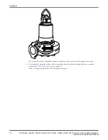
Page 49: ...ion These requirements apply Use the pump dimensional drawing in order to ensure proper installation Provide a suitable barrier around the work area for example a guard rail Check the explosion risk before you weld or use electric hand tools Remove all debris from the inlet piping system before you install the pump Remove all debris from the pump sump before you install the pump Fasteners WARNING ...

Page 50: ...d regulating the height of the level regulators Access frame with covers to which the upper guide bar bracket and cable holder can be attached Discharge connection for connecting the pump to the discharge line the discharge connection has a flange which fits the pump casing flange and a bracket for attaching the guide equipment Bushings for vibration damping between the guide bars and the discharg...

Page 51: ...ables a Make sure that the cables cannot be sucked into the inlet of the pump Support straps are required for deep installations b Run the cables up to the electrical panel or junction box and connect them according to the separate instructions 11 Clean all debris from the sump before filling the sump Install with S installation In the S installation the pump is transportable and intended to opera...

Page 52: ...ards The following items are required Support stand for anchoring the pump to a base Plate or base stand with anchor bolts for anchoring the pump to a concrete base Inlet elbow for connecting the suction line and discharge line Shut off valves to permit the pump to be removed for service Air vent on the discharge side between the pump and the check valve WARNING Never remove the inspection cover d...

Page 53: ...must have the proper rating and the pump overload protection motor protection breaker must be connected and set to the rated current according to the data plate and if applicable the cable chart The starting current in direct on line starting can be up to six times higher than the rated current The fuse rating and the cables must be in accordance with the local rules and regulations If intermitten...

Page 54: ...es 1 Connect the monitoring equipment 2 Connect the cable to the terminal board If you have the MAS system connect the cable to its terminal board according to the illustration and table in MAS sensor connections page 53 NOTICE As the cable ends are sealed to eliminate moisture entrainment during transport and storage no wire markings for the sensors at the outlet end of the cable are made at the ...

Page 55: ...ound the cable c Fasten the connection flange to the entrance flange Make sure that the seal sleeve is not misaligned with the rubber sleeve and that the entrance flange supports the cable so that it cannot be excessively bent 5 Connect the starter equipment a Connect the power cable to the starter equipment according to the diagram in Power cable phase sequence page 51 b Connect the auxiliary cab...

Page 56: ...d Brown Red Black L1 2 L2 cable lead Black Black Black L2 3 L3 cable lead Grey White Black L3 4 Earth PE or ground cable lead Green Yellow Green Yellow Green Yellow Not shown Ground check GC cable lead Yellow 5 Power cable to pump Installation 52 C3300 6x5 C R3231 C3240 C3306 C3312 C3351 C3356 C3400 C3501 C3531 C3602 C3800 Installation Operation and Maintenance Manual ...
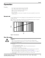
Page 57: ... S TATOR LEA KAGE CONNECTION HOUSING TEMP MAIN BEARING TEMP 1 WINDING WINDING TEMP TEMP SUPPO RT BEARING TEMP 3 WINDNING TEMP 2 WINDNING WS000508A Figure 18 Connections at the pump Arrows indicate SUBCAB cable lead numbers Installation C3300 6x5 C R3231 C3240 C3306 C3312 C3351 C3356 C3400 C3501 C3531 C3602 C3800 Installation Operation and Maintenance Manual 53 ...

Page 58: ... the stator housing3 1 1 1 2 2 2 Float switch in the junction box 9 7 7 2 Pt100 in the main bearing4 3 3 3 4 4 4 Pt100 in the support bearing 37 17 38 18 Thermal switches or thermistors in the stator 5 5 5 6 6 6 CLS sensor in the oil housing 33 19 34 20 Pt100 in the stator winding 1 19 8 8 4 3 The leakage sensors in the stator housing and the junction box use the same terminal terminal 2 on the te...

Page 59: ...ovides information for connecting CAS to 6X5 7X5 8X5 and 9X5 drive units in the following situations A replacement pump is being installed at an older pump station where the CAS system is still functioning A replacement monitoring system is needed at an older pump station where the pump is still working but the CAS system must be replaced The CAS monitoring system is no longer available as a spare...

Page 60: ...G WINDING TEMP TEMP SUPPO RT BEARING TEMP 3 WINDNING TEMP 2 WINDNING WS000508A Figure 20 Connections at the pump Arrows indicate SUBCAB cable lead numbers MAS 711 MRM 01 This section provides connection diagrams for replacing the CAS monitoring system with the MAS 711 together with the MRM 01 relay Installation 56 C3300 6x5 C R3231 C3240 C3306 C3312 C3351 C3356 C3400 C3501 C3531 C3602 C3800 Instal...

Page 61: ...ctions at the MAS 711 MRM 01 base units Description Part number Unit MAS 711 and MRM 01 40 50 15 45 MAS 711 40 50 11 41 MRM 01 40 50 15 36 CAS connected pumps The CAS system is no longer available as a spare part This section provides connection diagrams for replacement pumps at stations equipped with a functioning CAS monitoring system Installation C3300 6x5 C R3231 C3240 C3306 C3312 C3351 C3356 ...

Page 62: ...r housing 1 1 1 2 2 2 Pt100 in the main bearing 3 3 3 4 4 4 Thermal switches or thermistors in the stator 5 5 5 6 6 6 Pt100 in the support bearing 37 7 7 38 8 8 Float switch in the junction box 9 9 9 10 10 10 CLS sensor in the oil housing 33 11 11 34 12 12 Pt100 in the stator winding 1 19 19 20 20 Pt100 in the stator winding 2 21 21 22 22 Pt100 in the stator winding 3 23 23 24 24 Cable charts Elec...

Page 63: ...to 1 1 kV D connection 3 pole terminal 1 or 2 cables SUBCAB GC GC V2 W1 W2 U1 V1 V W U U2 L2 L3 L1 10002d D L2 L3 L1 GC 3 Figure 23 Schematic diagram This cable chart shows the connection for drives units in the 6X5 series U1 V1 W1 L1 L3 L2 Figure 24 Drive units 605 615 665 675 This cable chart shows the connection for drive units in the 8X5 and 9X5 series also drive units 7X5 with large junction ...

Page 64: ...1 U1 U2 L2 L3 L1 Figure 26 Schematic diagram Connection for 6X5 and 7X5 drives units W1 V1 U1 W2 U2 V2 L2 L3 L1 Figure 27 Drive units 605 615 665 675 705 715 735 745 765 775 Installation 60 C3300 6x5 C R3231 C3240 C3306 C3312 C3351 C3356 C3400 C3501 C3531 C3602 C3800 Installation Operation and Maintenance Manual ...
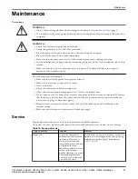
Page 65: ... 665 675 705 715 735 745 765 775 Connection for 8X5 and 9X5 drive units also drive units 7X5 with large junction box see Connection houses junction boxes in 7X5 drive units page 66 L2 L3 L1 V2 W1 U2 V1 U1 W2 Figure 30 2 cables drive units 805 815 835 845 865 875 885 895 905 915 935 945 965 975 7X5 with large junction box Installation C3300 6x5 C R3231 C3240 C3306 C3312 C3351 C3356 C3400 C3501 C353...

Page 66: ...for 8X5 and 9X5 drive units also drive units 7X5 with large junction box see Connection houses junction boxes in 7X5 drive units page 66 L3 L1 L2 U1 W2 U2 V1 V2 W1 Figure 32 3 cables drive units 805 815 835 845 865 875 885 895 905 915 935 945 965 975 7X5 with large junction box Installation 62 C3300 6x5 C R3231 C3240 C3306 C3312 C3351 C3356 C3400 C3501 C3531 C3602 C3800 Installation Operation and ...

Page 67: ... 765 775 This cable chart shows the connection for drive units in the 8X5 and 9X5 series also drive units 7X5 with large junction box see Connection houses junction boxes in 7X5 drive units page 66 L2 L3 L1 V2 W1 V1 U2 W2 U1 Figure 35 Drive units 805 815 835 845 865 875 885 895 905 915 935 945 965 975 7X5 with large junction box Installation C3300 6x5 C R3231 C3240 C3306 C3312 C3351 C3356 C3400 C3...

Page 68: ...n for drive units in the 8X5 and 9X5 series also drive units 7X5 with large junction box see Connection houses junction boxes in 7X5 drive units page 66 L2 L3 L1 U2 V1 U1 W2 V2 W1 Figure 38 Drive units 805 815 835 845 865 875 885 895 905 915 935 945 965 975 7X5 with large junction box Drive units 1 2 6 6 kV The connection diagrams for medium voltage 1 2 6 6 kV drive units are shown in the table be...

Page 69: ...mm2 350 1 59 Ø 33 0 37 0 This table shows the minimum bending radius weight and outer diameter for SUBCAB power cables Table 15 SUBCAB power cables Cable Minimum bending radius in mm Weight in kg m Outer diameter minimum maximum in mm 4 G 16 mm2 260 1 25 Ø 26 0 28 0 4 G 25 mm2 320 1 9 Ø 32 5 34 5 4 G 35 mm2 360 2 5 Ø 36 5 38 5 4 G 50 mm2 410 3 4 Ø 41 0 45 0 4 G 70 mm2 450 4 5 Ø 45 0 49 0 4 G 95 mm...

Page 70: ...x1 5 560 6 Ø 52 0 56 0 S3x185 3x95 3 4x1 5 670 9 5 Ø 65 0 69 0 This table shows the minimum bending radius weight and outer diameter for HSP NTSCGEWTOEUS 1 2 10 kV cables Table 18 HSP NTSCGEWTOEUS 1 2 10 kV Cable Minimum bending radius in mm Weight in kg m Outer diameter minimum maximum in mm 3x25 3x25 3 385 3 32 Ø 46 4 49 4 3x35 3x25 3 410 3 81 Ø 49 0 52 0 3x50 3x25 3 450 4 78 Ø 54 0 58 0 Connect...

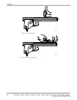
Page 71: ...il 4 Conductive layer 5 Conductor insulation 6 Conductive foil 7 Copper conductor 8 Shield wires 1 Peel off 420 mm of the cable casing at the connection ends of the cable a Make the vertical cut 420 mm 16 5 in F000173 b Make the horizontal cut Installation C3300 6x5 C R3231 C3240 C3306 C3312 C3351 C3356 C3400 C3501 C3531 C3602 C3800 Installation Operation and Maintenance Manual 67 ...
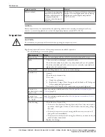
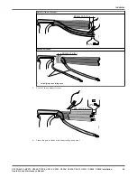
Page 72: ...c Remove the cable casing F000175 2 Peel off the casing from the leads Installation 68 C3300 6x5 C R3231 C3240 C3306 C3312 C3351 C3356 C3400 C3501 C3531 C3602 C3800 Installation Operation and Maintenance Manual ...

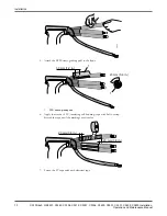
Page 73: ... Yellow green insulating hose 3 Peel off the conductive layer 200 mm 7 9 in 5 mm 0 2 in F000178 4 Clean the power leads with chemically pure petrol Installation C3300 6x5 C R3231 C3240 C3306 C3312 C3351 C3356 C3400 C3501 C3531 C3602 C3800 Installation Operation and Maintenance Manual 69 ...

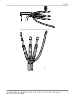
Page 74: ...ur turns of IV insulating self bonding tape with half overlap Stretch the tape until the markings are circular 20 mm 0 8 in 20 mm 0 8 in 7 Fasten the IV tape ends with electrical tape Installation 70 C3300 6x5 C R3231 C3240 C3306 C3312 C3351 C3356 C3400 C3501 C3531 C3602 C3800 Installation Operation and Maintenance Manual ...

Page 75: ...8 Fasten the connection shoes and connection eyes to the leads F000183 Installation C3300 6x5 C R3231 C3240 C3306 C3312 C3351 C3356 C3400 C3501 C3531 C3602 C3800 Installation Operation and Maintenance Manual 71 ...

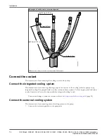
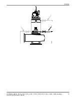
Page 76: ... integrated cooling The pumped fluid is used as coolant in these systems Coolant supply inlet and return outlet lines do not have to be connected when integrated cooling is used Connect the fittings to drain the coolant as shown in Fittings needed to drain cooling jacket page 38 Connect the external cooling system This instruction is for connecting external cooling systems to the pump 1 Connect th...

Page 77: ...1 F000450 2 3 Installation C3300 6x5 C R3231 C3240 C3306 C3312 C3351 C3356 C3400 C3501 C3531 C3602 C3800 Installation Operation and Maintenance Manual 73 ...
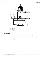
Page 78: ...35 845 862 872 865 875 882 892 885 895 905 915 935 945 950 960 965 975 985 995 F000457 2 Connect the coolant return line to the outlet on the pump Installation 74 C3300 6x5 C R3231 C3240 C3306 C3312 C3351 C3356 C3400 C3501 C3531 C3602 C3800 Installation Operation and Maintenance Manual ...
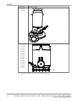
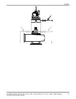
Page 79: ...1 F000451 2 3 Installation C3300 6x5 C R3231 C3240 C3306 C3312 C3351 C3356 C3400 C3501 C3531 C3602 C3800 Installation Operation and Maintenance Manual 75 ...
Page 80: ... 875 882 892 885 895 905 915 935 945 950 960 965 975 985 995 F000458 3 Connect the fittings to drain the coolant see Fittings needed to drain cooling jacket page 38 Installation 76 C3300 6x5 C R3231 C3240 C3306 C3312 C3351 C3356 C3400 C3501 C3531 C3602 C3800 Installation Operation and Maintenance Manual ...

Page 81: ... page 41 2 Connect the seal flushing supply water to the pump See Connections for seal flushing page 43 Check the impeller rotation WARNING The starting jerk can be powerful 1 Start the motor 2 Stop the motor after a few seconds 3 Check that the impeller rotates according to this illustration The figure shows a generic impeller pump Installation C3300 6x5 C R3231 C3240 C3306 C3312 C3351 C3356 C340...

Page 82: ...er rotates in the wrong direction check that the phase leads are correctly connected See Power cable phase sequence page 51 After re connecting phase leads do this procedure again Installation 78 C3300 6x5 C R3231 C3240 C3306 C3312 C3351 C3356 C3400 C3501 C3531 C3602 C3800 Installation Operation and Maintenance Manual ...
Page 83: ... pump WARNING Make sure that the pump cannot roll or fall over and injure people or damage property Make sure nobody is close to the pump when it is started The pump will jerk in the opposite direction of the impeller rotation 1 Check that a The monitoring equipment works b The starter equipment is installed according to the manufacturer s instructions c All the alarms are functioning d The oil is...

Page 84: ...s installed in such a way that it can be exposed to temperatures at or below the freezing point that is the pump is not totally submerged then special modifications must be made to the pump and the installation For more information please contact your ITT representative Operation 80 C3300 6x5 C R3231 C3240 C3306 C3312 C3351 C3356 C3400 C3501 C3531 C3602 C3800 Installation Operation and Maintenance...

Page 85: ...em Do not open any vent or drain valves or remove any plugs while the system is pressurized Make sure that the pump is isolated from the system and that pressure is relieved before you disassemble the pump remove plugs or disconnect piping Depressurize and empty the coolant system for T and Z installations and all installations with external cooling Make sure electrical power is disconnected locke...

Page 86: ...ed and tightened to the correct torque Lifting handle Check the lifting handle for corrosion or other damage Junction box 1 General Check that it is clean and dry If it is wet a Check the cable entry b Replace the O rings New O rings should be fitted to all O ring seal joints opened during inspection 2 Terminal board Check that the connections are properly tightened Junction box insulation drive u...

Page 87: ...spection page 82 2 Do these additional steps Part to service Action Isolation check drive units up to 1 1 kV Check that the resistance between earth and phase lead is more than 5 MΩ Isolation check 1 2 6 6 kV drive units 1 Check that the resistance between earth and phase lead is above the minimum for the motor voltage Recommended test voltage 500 V DC max 1000 V DC The resistance value is related...

Page 88: ...ves 1 Check that the resistance between the earth ground and phase lead is more than 5 megohms Use a 1000 V DC megger The resistance should preferably be more than 50 MΩ 2 Keep a record of the results Check the junction box insulation 1 2 6 6 kV drives 1 Check that the resistance value is a minimum of 5 megohms kV at a temperature of 25ºC 77ºF Use a 1000 V DC megger Recommended test voltage 500 V ...

Page 89: ...in order to be checked However it will not be damaged if plus and minus are switched b Use a multimeter as an ammeter and connect it in series with the sensor c If the sensor is accessible check the alarm function by gripping the sensor in your hand Skin and blood tissue contain a high content of water For interpretation of the CLS measurement results seeSensors page 27 Empty the coolant integrate...

Page 90: ... 2 in the figure below 3 Depressurize the cooling system by opening the stop cock marked 3 in the figure below if applicable 4 Remove the coolant filling plug and empty the coolant through the drainage pipe marked 4 in the figure below 5 After you empty the cooling jacket on P and S installations run the pump dry for no more than 30 seconds to expel all water from the impeller area Maintenance 86 ...

Page 91: ...th a tasteless odorless medical white oil of paraffin type that fulfills FDA 172 878 The replacement oil must have a viscosity class of ISO VG 15 35 Examples of suitable oil types are the following Mobile Whiterex Shell Ondina Maintenance C3300 6x5 C R3231 C3240 C3306 C3312 C3351 C3356 C3400 C3501 C3531 C3602 C3800 Installation Operation and Maintenance Manual 87 ...

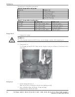
Page 92: ...1 C3602 C3800 9 liters 9 5 quarts Empty the oil 1 Unscrew the oil plugs WARNING The oil housing may be pressurized Hold a rag over the oil plug to prevent oil from spraying out 2 Pump out the oil Use oil drainage pump 83 95 42 Make sure that the plastic tube goes all the way to the bottom of the oil housing Fill with oil 1 Fill the housing with new oil Make sure that the oil reaches the oil holes ...

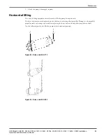
Page 93: ... propeller Damage to the impeller propeller seals or bearings can result from placing the drive unit on the impeller propeller or shaft Use the following method to lift the pump in the horizontal position Figure 44 Drive units 605 775 Figure 45 Drive units 805 995 Maintenance C3300 6x5 C R3231 C3240 C3306 C3312 C3351 C3356 C3400 C3501 C3531 C3602 C3800 Installation Operation and Maintenance Manual...

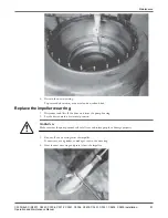
Page 94: ...re will be easier if the suction cover is first heated and or the wear ring is cooled down 1 Disconnect and lift off the drive unit with pump housing from the suction cover 2 Lay the drive unit in a horizontal position WARNING Make sure that the pump cannot roll or fall over and injure people or damage property 3 Remove the wear ring by using a crow bar Maintenance 90 C3300 6x5 C R3231 C3240 C3306...

Page 95: ...zontal position WARNING Make sure that the pump cannot roll or fall over and injure people or damage property 3 Knock off the wear ring from the impeller If necessary use a grinder to make grooves in the wear ring 4 Heat the new wear ring and press it onto the impeller Maintenance C3300 6x5 C R3231 C3240 C3306 C3312 C3351 C3356 C3400 C3501 C3531 C3602 C3800 Installation Operation and Maintenance M...

Page 96: ... a Disconnect and lift off the drive unit from the pump housing b Lay the drive unit in a horizontal position Make sure it cannot roll WARNING Make sure that the pump cannot roll or fall over and injure people or damage property 2 Depending on which pump model you have do one of the following Pump Action C3300 6x5 LT and MT Remove the centre screw in the impeller sealing washer The locking assembl...

Page 97: ... between the pump housing and the suction cover Minimum distance 30 mm 1 18 in 4 Remove the two screws for the impeller 5 Apply the puller unit 4917400 according to the illustration and pull off the impeller Remove the suction cover and the impeller 6 Disconnect and lift off the drive unit from the pump housing The locking assembly is now accessible for removal R3231 Remove the sealing washer unit...

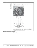
Page 98: ...er sealing washer C to remove the washer C Figure 47 C3240 C3312 C3351 C3400 C3501 C3531 C3602 or C3800 The locking assembly is now accessible for removal Remove the locking assembly 1 Remove the locking assembly Maintenance 94 C3300 6x5 C R3231 C3240 C3306 C3312 C3351 C3356 C3400 C3501 C3531 C3602 C3800 Installation Operation and Maintenance Manual ...
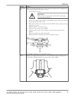
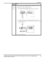
Page 99: ...d do as follows a Loosen the inner ring by tapping it lightly as shown in the illustration b If tapping did not loosen the ring replace the three light colored screws with three M10 draw bolts for 84 59 12 and 84 59 13 or M12 draw bolts for 84 59 14 and 84 59 17 M10 M12 2 Remove the locking assembly Maintenance C3300 6x5 C R3231 C3240 C3306 C3312 C3351 C3356 C3400 C3501 C3531 C3602 C3800 Installat...

Page 100: ...See illustration below 3 Remove the locking assembly 2 Pull off the impeller a Fit the tools required for impeller removal according to the tool list for the appropriate pump See Tools page 102 b Pull off the impeller Use the hydraulic unit with the partially threaded screw in the Basic kits for removal or screw unit 602 31 00 for C3800 Maintenance 96 C3300 6x5 C R3231 C3240 C3306 C3312 C3351 C335...

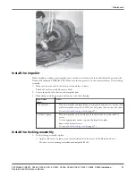
Page 101: ...shaft and press it onto the shaft with the impeller screw For C3300 6x5 HT press the hub onto the shaft 2 Go on to Install the locking assembly page 97 Other C pump 1 Place the impeller on the shaft and fit the hydraulic tool with the M16 screw 2 Use the appropriate washer to press the impeller in place 3 Remove the hydraulic tool 4 Go on to Install the locking assembly page 97 Install the locking...

Page 102: ...ne of the slots in the washer and into one of the light colored screws in the locking assembly b Fit the impeller screw or the screw unit with hydraulic tool if applicable through the center hole in the washer and into the shaft end See Tools page 102 for the screw screw unit for the respective pump c Tighten the centre screw so that the washer keeps the locking assembly and the impeller in place ...

Page 103: ...ler you must do the following 1 Check that the impeller can be rotated by hand 2 Check the zinc anodes if applicable to make sure they are large enough and intact Replace after approximately 75 consumption 3 Fit the drive unit to the pump housing Make sure that the pump housing has the correct orientation Remember the O ring between the pump housing and the drive unit More extensive repairs requir...

Page 104: ...5 960 110 1 9 5 13 3 12 8 16 2 10 6 14 4 11 7 15 84 60 11 C3351 C3531 C3602 with drive units 965 995 and C3800 110 1 5 9 3 8 12 2 6 10 4 7 11 Tightening torques The table below gives the torque which should be used in each stage of the bolt tightening process Maintenance 100 C3300 6x5 C R3231 C3240 C3306 C3312 C3351 C3356 C3400 C3501 C3531 C3602 C3800 Installation Operation and Maintenance Manual ...
Page 105: ...s Torque values Screws and nuts Property class M4 M5 M6 M8 M10 M12 M16 M20 M24 M30 Stainless steel A2 and A4 torque Nm ft lbs 70 805 2 7 2 5 4 4 9 3 6 9 22 16 44 32 76 56 187 138 364 268 629 464 1240 915 Carbon steel and alloyed steel torque Nm ft lbs 8 8 2 9 2 1 5 7 4 2 9 8 7 2 24 18 47 35 81 60 194 143 385 285 665 490 1310 966 10 9 4 0 2 9 8 1 6 14 10 3 33 24 3 65 48 114 84 277 204 541 399 935 6...

Page 106: ...no Denomination Range of use 83 95 42 Oil drainage pumps Drainage pumps for emptying oil housing 84 13 68 Hydraulic unit Table 22 R3231 Part no Denomination Range of use 436 19 00 Basic kit II 436 74 00 Impeller tool Table 23 C3300 6X5 LT Part no Denomination Range of use 84 20 49 Puller 479 23 00 Extension 479 25 00 Washer Table 24 C3300 6X5 MT Part no Denomination Range of use 400 54 03 Dismount...

Page 107: ...le 29 C3531 C3602 Part no Denomination Range of use 332 91 00 Stop spring removing tool 399 41 00 Mounting tool unit for shaft Ø75 and Ø90 mm Mounting the seal 576 83 01 Washer for shaft Ø75 7X5 drive units Mounting the locking assembly 576 83 02 Washer for shaft Ø90 mm for 8X5 905 915 drive units Mounting the locking assembly 576 83 03 Washer for shaft Ø110 mm for 905 960 drive units Mounting the...

Page 108: ...ller tool 602 31 00 Screw unit removal 660 49 00 Impeller tool mounting The locking assembly and the impeller Maintenance 104 C3300 6x5 C R3231 C3240 C3306 C3312 C3351 C3356 C3400 C3501 C3531 C3602 C3800 Installation Operation and Maintenance Manual ...
Page 109: ...ude the following Pump controller Control panels Starters MAS and other monitoring relays See your ITT representative for further information Options The following options are available Zinc anodes for corrosion protection Special coating system with epoxy base coat for demanding environments Power monitoring Monitoring options for temperature vibration and water in the oil housing Materials Impel...

Page 110: ...7 ASTM A 536 No 80 55 06 Stainless steel duplex M0344 2324 12 EN 10283 2010 No 1 4474 ASTM CD 4MCuN Pump housing Table 35 C3231 C3240 C3300 C3306 C3312 C3351 C3356 C3400 C3800 Available materials Flygt material number Standard Europe USA Cast iron M0314 0125 00 EN 1561 1997 No JL 1040 ASTM A 48 No 35 B Table 36 C3501 C3531 Available materials Flygt material number Standard Europe USA Cast iron sph...

Page 111: ...kness Flygt standard Standard Acrylic waterborne or alkyd solventborne Oxirane ester 2 pack 200 μm M0700 00 0004 Special option Epoxy Oxirane ester 2 pack 500 μm M0700 00 0005 Mounting related data Depth of immersion The maximum depth of immersion is 20 m 65 ft Weight See the dimensional drawing for pump weights Cables Table 38 C3231 C3300 C3306 C3356 SUBCAB Maximum voltage 600 1000 V intended for...

Page 112: ...oltage range Standard drive units Explosion proof drive units Maximum number of starts per hour Up to 1 1 kV 805 815 15 835 845 15 865 875 15 885 895 8 1 2 6 6 kV 862 872 15 882 892 8 C3300 Voltage range Standard drive units Explosion proof drive units Maximum number of starts per hour Up to 1 1 kV 605 615 15 665 675 15 C3306 Voltage range Standard drive units Explosion proof drive units Maximum n...

Page 113: ...starts per hour Up to 1 1 kV 605 615 15 665 675 15 705 715 15 735 745 15 765 775 15 C3400 Voltage range Standard drive units Explosion proof drive units Maximum number of starts per hour Up to 1 1 kV 705 715 15 735 745 15 765 775 15 805 815 15 835 845 15 865 875 15 885 895 8 1 2 6 6 kV 862 872 15 882 892 8 C3501 Voltage range Standard drive units Explosion proof drive units Maximum number of start...

Page 114: ... 865 875 15 885 895 8 905 915 8 935 945 8 1 2 6 6 kV 862 872 15 882 892 8 950 960 8 985 995 8 C3800 Voltage range Standard drive units Explosion proof drive units Maximum number of starts per hour Up to 1 1 kV 905 915 8 935 945 8 965 975 8 1 2 6 6 kV 950 960 8 985 995 8 Operational data Application limits Table 40 Process data Parameter Value Liquid temperature Max 40 C 105 F Depth of immersion Ma...

Page 115: ...gue temperature sensor Standard Leakage in the stator housing Float Switch Leakage Sensor FLS Standard Stator winding temperature See table below Standard Support bearing temperature Pt100 analogue temperature sensor Optional Water in oil Capacitive Leakage Sensor CLS Optional Vibration VIS 10 Optional Power monitoring Separate electronic instrument using three current transformers Optional Pump c...

Page 116: ... PTC thermistors 3 3 3 sensors are connected in series and 3 are built in reserves Pt100 analogue temperature sensors in all 3 stator windings 3 3 Each winding has 1 sensor connected and 1 built in reserve Technical Reference 112 C3300 6x5 C R3231 C3240 C3306 C3312 C3351 C3356 C3400 C3501 C3531 C3602 C3800 Installation Operation and Maintenance Manual ...

Page 117: ...5 190 1380 0 85 705 715 400 125 234 1525 0 83 735 745 400 170 300 2020 0 87 455 1480 605 615 400 70 127 800 0 86 665 675 400 85 153 1025 0 86 665 675 400 105 190 1380 0 85 705 715 400 125 234 1525 0 83 735 745 400 170 300 2020 0 87 655 985 605 615 400 58 118 660 0 78 WS000462A H m Q l s Figure 48 C3231 50 Hz low voltage 1 of 2 C3231 Motor rating and performance 50 Hz C3300 6x5 C R3231 C3240 C3306 ...

Page 118: ...Q H m Figure 49 C3231 50 Hz low voltage 2 of 2 C3231 Motor rating and performance 50 Hz 114 C3300 6x5 C R3231 C3240 C3306 C3312 C3351 C3356 C3400 C3501 C3531 C3602 C3800 Installation Operation and Maintenance Manual ...
Page 119: ...os φ 450 1490 805 815 400 215 375 2920 0 88 835 845 400 290 515 4505 0 86 865 875 400 375 650 5420 0 88 0 50 100 150 200 250 300 350 400 450 l s 0 10 20 30 40 50 60 70 80 90 100 110 120 130 m WS000463A 450 H Q Figure 50 C3240 50 Hz low voltage C3240 Motor rating and performance 50 Hz C3300 6x5 C R3231 C3240 C3306 C3312 C3351 C3356 C3400 C3501 C3531 C3602 C3800 Installation Operation and Maintenanc...

Page 120: ...00 215 47 360 0 84 882 892 3300 290 63 475 0 84 3300 345 74 505 0 85 6000 275 33 260 0 84 6000 325 39 284 0 84 0 50 100 150 200 250 300 350 400 450 l s 0 10 20 30 40 50 60 70 80 90 100 110 120 130 m WS000463A 450 H Q Figure 51 C3240 50 Hz medium voltage C3240 Motor rating and performance 50 Hz 116 C3300 6x5 C R3231 C3240 C3306 C3312 C3351 C3356 C3400 C3501 C3531 C3602 C3800 Installation Operation ...

Page 121: ...ting current A Power factor cos φ 601 985 605 615 400 58 118 660 0 78 665 675 400 75 150 835 0 79 665 675 400 90 185 1160 0 76 460 1480 605 615 400 70 127 800 0 86 WS000597A Figure 52 C3300 50 Hz low voltage 1 of 2 C3300 Motor rating and performance 50 Hz C3300 6x5 C R3231 C3240 C3306 C3312 C3351 C3356 C3400 C3501 C3531 C3602 C3800 Installation Operation and Maintenance Manual 117 ...

Page 122: ... Figure 53 C3300 50 Hz low voltage 2 of 2 C3300 Motor rating and performance 50 Hz 118 C3300 6x5 C R3231 C3240 C3306 C3312 C3351 C3356 C3400 C3501 C3531 C3602 C3800 Installation Operation and Maintenance Manual ...

Page 123: ...45 400 170 300 2020 0 87 765 775 400 215 395 2945 0 83 610 1480 605 615 400 58 118 660 0 78 665 675 400 75 150 835 0 79 665 675 400 90 185 1160 0 76 705 715 400 100 202 1150 0 78 735 745 400 140 268 1545 0 81 WS000464A l s Q H m Figure 54 C3306 50 Hz low voltage C3306 Motor rating and performance 50 Hz C3300 6x5 C R3231 C3240 C3306 C3312 C3351 C3356 C3400 C3501 C3531 C3602 C3800 Installation Opera...

Page 124: ...os φ 630 735 705 715 400 55 107 505 0 82 400 90 182 775 0 79 830 985 705 715 400 100 202 1150 0 78 735 745 400 140 268 1545 0 81 765 775 400 180 360 2215 0 77 835 845 400 250 465 2645 0 82 WS000466A l s Q H m Figure 55 C3312 50 Hz low voltage C3312 Motor rating and performance 50 Hz 120 C3300 6x5 C R3231 C3240 C3306 C3312 C3351 C3356 C3400 C3501 C3531 C3602 C3800 Installation Operation and Mainten...

Page 125: ...30 990 862 872 3300 190 41 262 0 85 6000 180 22 140 0 85 882 892 3300 250 54 390 0 85 6000 240 29 218 0 84 0 100 200 300 400 500 600 l s 0 10 20 30 40 50 60 m 630 WS000488A Q H Figure 56 C3312 50 Hz medium voltage C3312 Motor rating and performance 50 Hz C3300 6x5 C R3231 C3240 C3306 C3312 C3351 C3356 C3400 C3501 C3531 C3602 C3800 Installation Operation and Maintenance Manual 121 ...

Page 126: ... A Starting current A Power factor cos φ 650 990 905 915 400 290 525 3115 0 84 400 375 685 4180 0 83 935 945 400 460 840 5190 0 82 400 560 990 5580 0 85 WS000469A m l s Q H Figure 57 C3351 50 Hz low voltage C3351 Motor rating and performance 50 Hz 122 C3300 6x5 C R3231 C3240 C3306 C3312 C3351 C3356 C3400 C3501 C3531 C3602 C3800 Installation Operation and Maintenance Manual ...

Page 127: ...6000 380 46 288 0 84 445 54 340 0 84 520 61 370 0 86 3300 400 86 490 0 86 470 104 655 0 83 500 108 695 0 85 850 745 950 960 6000 215 28 151 0 83 270 33 190 0 82 3300 225 51 291 0 82 290 65 360 0 82 0 800 0 200 400 600 l s 10 20 30 40 50 60 70 80 m WS000470A 650 0 0 850 H Q Figure 58 C3351 50 Hz medium voltage C3351 Motor rating and performance 50 Hz C3300 6x5 C R3231 C3240 C3306 C3312 C3351 C3356 ...

Page 128: ...8 660 0 78 665 675 400 75 150 835 0 79 665 675 400 90 185 1160 0 76 705 715 400 100 202 1150 0 78 735 745 400 140 268 1545 0 81 765 775 400 209 345 2230 0 80 810 730 605 615 400 45 95 425 0 77 665 675 400 55 115 525 0 77 WS000474A l s Q H Figure 59 C3356 50 Hz low voltage C3356 Motor rating and performance 50 Hz 124 C3300 6x5 C R3231 C3240 C3306 C3312 C3351 C3356 C3400 C3501 C3531 C3602 C3800 Inst...

Page 129: ...5 400 90 227 940 0 64 830 730 705 715 400 90 182 775 0 79 735 745 400 125 245 1065 0 81 765 775 400 150 292 1330 0 81 805 815 400 160 305 1360 0 81 630 990 805 815 400 180 330 1765 0 83 835 845 400 250 465 2645 0 82 865 875 400 310 575 3370 0 82 WS000425A 200 400 600 800 1000 1200 l s Q 1400 1230 1030 830 630 H 20 0 0 5 10 15 25 45 35 30 40 50 m Figure 60 C3400 50 Hz low voltage C3400 motor rating...

Page 130: ...2 140 0 85 3300 190 41 262 0 85 882 892 6000 240 29 218 0 84 3300 250 54 390 0 85 6000 305 37 292 0 83 3300 340 72 510 0 86 830 740 862 872 6000 150 19 109 0 81 3300 180 22 140 0 85 WS000476A m H Q l s Figure 61 C3400 50 Hz medium voltage C3400 motor rating and performance 50 Hz 126 C3300 6x5 C R3231 C3240 C3306 C3312 C3351 C3356 C3400 C3501 C3531 C3602 C3800 Installation Operation and Maintenance...

Page 131: ... 400 60 158 550 0 61 765 775 400 80 207 710 0 62 805 815 400 100 256 1025 0 61 1030 590 735 745 400 90 227 940 0 64 765 775 400 110 250 1110 0 70 805 815 400 125 269 1245 0 73 835 845 400 170 380 1920 0 70 830 730 765 775 400 150 292 1330 0 81 835 845 400 215 435 2385 0 76 865 875 400 275 535 2730 0 79 WS000478A l s Q H m Figure 62 C3501 50 Hz low voltage C3501 Motor rating and performance 50 Hz C...

Page 132: ... 165 23 103 0 74 3300 175 44 184 0 75 830 740 862 872 6000 150 19 109 0 81 3300 165 38 214 0 81 882 892 6000 185 23 140 0 81 3300 215 52 320 0 78 6000 235 30 179 0 79 3300 250 57 320 0 81 0 200 400 600 800 1000 1200 1400 1600 1800 l s 0 2 4 6 8 10 12 14 16 18 20 22 24 26 28 m 1230 1030 Q H 830 WS000479A Figure 63 C3501 50 Hz medium voltage C3501 Motor rating and performance 50 Hz 128 C3300 6x5 C R...

Page 133: ... 74 735 745 400 90 222 880 0 68 765 775 400 110 230 920 0 73 805 815 400 125 275 1170 0 75 835 845 400 170 380 1800 0 73 865 875 400 215 460 1915 0 76 840 735 735 745 400 125 245 1065 0 81 805 815 400 160 305 1360 0 81 835 845 400 215 460 2385 0 77 865 875 400 275 535 2730 0 79 905 915 400 340 610 3295 0 84 935 945 400 400 730 4510 0 82 640 990 835 845 400 250 475 2495 0 84 865 875 400 310 575 337...

Page 134: ...483A Q H m l s Figure 64 C3531 50 Hz low voltage 1 of 2 C3531 Motor rating and performance 50 Hz 130 C3300 6x5 C R3231 C3240 C3306 C3312 C3351 C3356 C3400 C3501 C3531 C3602 C3800 Installation Operation and Maintenance Manual ...

Page 135: ...r factor cos φ 1240 495 862 872 6000 110 19 82 0 62 3300 120 36 148 0 64 882 892 6000 130 21 94 0 67 3300 140 40 142 0 68 1040 595 862 872 6000 130 21 94 0 67 3300 140 40 172 0 68 882 892 6000 165 23 103 0 74 3300 175 44 184 0 75 6000 205 28 148 0 74 3300 225 56 276 0 75 C3531 Motor rating and performance 50 Hz C3300 6x5 C R3231 C3240 C3306 C3312 C3351 C3356 C3400 C3501 C3531 C3602 C3800 Installat...

Page 136: ... 6000 330 42 253 0 81 3300 350 79 460 0 82 6000 380 47 285 0 82 3300 400 89 495 0 83 640 990 882 892 6000 240 29 218 0 84 3300 250 54 390 0 85 6000 305 37 292 0 83 3300 340 72 510 0 86 950 960 6000 250 30 178 0 84 3300 265 58 330 0 84 6000 315 38 228 0 85 3300 340 76 455 0 82 985 995 6000 380 46 288 0 84 3300 400 86 490 0 86 6000 445 54 340 0 84 3300 470 104 655 0 83 3300 520 112 695 0 85 6000 520...

Page 137: ... 1240 1040 840 640 Figure 66 C3531 50 Hz medium voltage C3531 Motor rating and performance 50 Hz C3300 6x5 C R3231 C3240 C3306 C3312 C3351 C3356 C3400 C3501 C3531 C3602 C3800 Installation Operation and Maintenance Manual 133 ...

Page 138: ...0 61 1040 590 765 775 400 110 250 1110 0 70 805 815 400 125 269 1245 0 73 835 845 400 170 380 1920 0 70 865 875 400 215 450 2045 0 74 905 915 400 250 475 2465 0 80 840 740 835 845 400 215 435 2385 0 76 865 875 400 275 535 2730 0 79 905 915 400 340 610 3295 0 84 935 945 400 400 730 4510 0 82 400 460 835 5180 0 83 5 10 15 20 25 30 35 m 0 200 400 600 800 1000 1200 1400 1600 1800 2000 2200 l s 0 H Q W...

Page 139: ...62 0 72 882 892 6000 165 23 103 0 74 3300 175 44 184 0 75 6000 205 28 148 0 74 3300 225 56 276 0 75 840 745 882 892 6000 185 23 140 0 81 3300 215 52 320 0 78 6000 235 30 179 0 79 3300 250 57 320 0 81 950 960 6000 215 27 151 0 83 3300 225 51 291 0 82 6000 270 33 190 0 82 3300 290 65 360 0 82 985 995 6000 330 42 253 0 81 3300 350 79 460 0 82 6000 380 47 285 0 82 3300 400 89 495 0 83 6000 440 55 335 ...

Page 140: ... 1800 2000 2200 l s 0 H Q WS000489A 840 1440 1240 1040 Figure 68 C3602 50 Hz medium voltage C3602 Motor rating and performance 50 Hz 136 C3300 6x5 C R3231 C3240 C3306 C3312 C3351 C3356 C3400 C3501 C3531 C3602 C3800 Installation Operation and Maintenance Manual ...

Page 141: ...5 1040 595 905 915 400 325 615 3075 0 80 935 945 400 375 735 4080 0 77 400 450 815 3470 0 84 965 975 400 550 1045 5555 0 79 840 740 935 945 400 400 730 4510 0 82 400 460 835 5180 0 83 965 975 400 560 985 5875 0 85 0 500 1000 1500 2000 2500 3000 l s 0 4 8 12 16 20 24 28 32 m WS000490A Q 840 1040 1240 H Figure 69 C3800 50 Hz low voltage C3800 Motor rating and performance 50 Hz C3300 6x5 C R3231 C324...

Page 142: ...275 0 73 3300 285 73 320 0 73 1040 595 985 995 3300 285 65 335 0 82 3300 320 73 405 0 81 3300 400 90 500 0 82 840 740 985 995 3300 400 89 495 0 83 3300 460 102 570 0 83 0 0 500 1000 1500 2000 2500 3000 l s 4 8 12 16 20 24 28 m WS000491A 1040 1240 H Q 840 Figure 70 C3800 50 Hz medium voltage C3800 Motor rating and performance 50 Hz 138 C3300 6x5 C R3231 C3240 C3306 C3312 C3351 C3356 C3400 C3501 C35...

Page 143: ...60 186 284 2030 0 88 1785 765 775 460 250 385 2955 0 86 455 1780 705 715 460 138 220 1525 0 85 735 745 460 186 284 2030 0 88 1785 765 775 460 250 385 2955 0 86 630 1185 605 615 460 67 115 685 0 81 460 82 139 685 0 81 655 1185 605 615 460 67 115 685 0 81 460 82 139 685 0 81 WS000460A GPM H Q Figure 71 C3231 60 Hz low voltage C3231 Motor rating and performance 60 Hz C3300 6x5 C R3231 C3240 C3306 C33...

Page 144: ... 0 88 600 455 410 3950 0 84 865 875 460 580 635 5380 0 90 600 580 505 4755 0 86 0 50 100 150 200 250 300 350 400 450 l s 0 1000 2000 3000 4000 5000 6000 7000 GPM 0 10 20 30 40 50 60 70 80 90 100 110 120 130 140 150 160 170 180 m 0 50 100 150 200 250 300 350 400 450 500 550 600 ft H Q 450 WS000406A Figure 72 C3240 60 Hz low voltage C3240 Motor rating and performance 60 Hz 140 C3300 6x5 C R3231 C324...

Page 145: ...7 4160 540 68 505 0 85 0 50 100 150 200 250 300 350 400 450 l s 0 1000 2000 3000 4000 5000 6000 7000 GPM 0 10 20 30 40 50 60 70 80 90 100 110 120 130 140 150 160 170 180 m 0 50 100 150 200 250 300 350 400 450 500 550 600 ft H Q WS000412A 450 Figure 73 C3240 60 Hz medium voltage C3240 Motor rating and performance 60 Hz C3300 6x5 C R3231 C3240 C3306 C3312 C3351 C3356 C3400 C3501 C3531 C3602 C3800 In...

Page 146: ...111 550 0 79 601 1185 665 675 460 82 139 865 0 81 665 675 460 104 179 1195 0 79 640 1185 605 615 460 67 115 685 0 81 665 675 460 82 139 865 0 81 460 1780 605 615 460 75 117 810 0 87 665 675 460 97 149 1035 0 87 665 675 460 119 183 1395 0 87 WS000599A GPM Q Figure 74 C3300 60 Hz low voltage 1 of 3 C3300 Motor rating and performance 60 Hz 142 C3300 6x5 C R3231 C3240 C3306 C3312 C3351 C3356 C3400 C35...

Page 147: ...w voltage 2 of 3 WS000601A GPM Q Figure 76 C3300 60 Hz low voltage 3 of 3 C3300 Motor rating and performance 60 Hz C3300 6x5 C R3231 C3240 C3306 C3312 C3351 C3356 C3400 C3501 C3531 C3602 C3800 Installation Operation and Maintenance Manual 143 ...

Page 148: ...5 0 83 631 1185 665 675 460 82 139 865 0 81 665 675 460 104 179 1195 0 79 705 715 460 112 190 1155 0 80 735 745 460 160 260 1555 0 83 810 880 605 615 460 52 92 440 0 79 665 675 460 63 111 550 0 79 665 675 460 75 128 665 0 80 831 880 605 615 460 52 92 440 0 79 665 675 460 63 111 550 0 79 665 675 460 75 128 665 0 80 WS000465A GPM Q H Figure 77 C3306 60 Hz low voltage C3306 Motor rating and performan...

Page 149: ...1 1090 0 82 600 185 178 840 0 82 765 775 460 230 285 1355 0 82 600 230 218 1025 0 82 630 1185 735 745 460 215 260 1555 0 83 600 215 206 1305 0 80 765 775 460 280 345 2230 0 80 600 280 263 1640 0 81 835 845 460 385 455 2670 0 84 600 385 345 1975 0 84 865 875 460 470 555 3405 0 84 600 470 435 2835 0 84 WS000467A GPM Q H 630 830 Figure 78 C3312 60 Hz low voltage C3312 Motor rating and performance 60 ...

Page 150: ...82 892 4160 405 52 395 0 85 4160 525 66 490 0 86 0 100 200 300 400 500 600 700 800 0 10 20 30 40 50 60 70 80 90 WS000468A 630 GPM 100000 50000 0 l s m ft H 100 80 60 40 20 0 120 140 160 180 200 220 240 260 280 300 Q Figure 79 C3312 60 Hz medium voltage C3312 Motor rating and performance 60 Hz 146 C3300 6x5 C R3231 C3240 C3306 C3312 C3351 C3356 C3400 C3501 C3531 C3602 C3800 Installation Operation a...

Page 151: ... 965 975 4160 1040 1145 5985 0 88 850 895 905 915 4160 430 495 2755 0 85 935 945 4160 525 605 3340 0 85 4160 620 720 4570 0 84 0 0 10 20 30 40 50 60 70 80 90 100 m 0 50 100 150 200 250 300 350 ft 100 200 300 400 500 600 700 800 900 1000 l s H Q 650 850 WS000471A 0 2000 4000 6000 8000 10000 12000 14000 GPM Figure 80 C3351 60 Hz low voltage C3351 Motor rating and performance 60 Hz C3300 6x5 C R3231 ...

Page 152: ...50 895 950 960 4160 350 47 284 0 82 4160 450 60 365 0 82 985 995 4160 540 72 455 0 81 0 0 10 20 30 40 50 60 70 80 90 m 0 50 100 150 200 250 300 ft 100 200 300 400 500 600 700 800 900 1000 l s H 850 650 WS000472A Q 0 2000 4000 6000 8000 10000 12000 14000 GPM Figure 81 C3351 60 Hz medium voltage C3351 Motor rating and performance 60 Hz 148 C3300 6x5 C R3231 C3240 C3306 C3312 C3351 C3356 C3400 C3501 ...

Page 153: ... 675 460 104 179 1195 0 79 705 715 460 112 190 1155 0 80 735 745 460 160 260 1555 0 83 765 775 460 209 345 2230 0 80 810 730 605 615 460 52 92 440 0 79 665 675 460 63 111 550 0 79 665 675 460 75 128 660 0 80 705 715 460 101 173 790 0 81 WS000473A GPM Q H Figure 82 C3356 60 Hz low voltage C3356 Motor rating and performance 60 Hz C3300 6x5 C R3231 C3240 C3306 C3312 C3351 C3356 C3400 C3501 C3531 C360...

Page 154: ...0 90 103 485 0 69 765 775 460 135 211 960 0 66 600 135 167 775 0 64 835 845 460 170 231 890 0 75 600 170 184 825 0 72 865 875 460 185 253 1275 0 74 600 185 210 1180 0 68 830 885 735 745 460 185 231 1085 0 82 600 185 178 840 0 82 765 775 460 230 285 1355 0 82 600 230 218 1025 0 82 835 845 460 335 430 2425 0 78 600 335 340 2045 0 75 865 875 460 415 515 2785 0 80 600 415 395 2150 0 80 630 1190 735 74...

Page 155: ...nt A Starting current A Power factor cos φ 1030 710 862 872 4160 220 33 147 0 75 830 895 862 872 4160 250 34 213 0 81 882 892 4160 330 46 305 0 79 4160 400 55 330 0 80 630 1195 882 892 4160 405 52 395 0 85 4160 525 66 490 0 86 C3400 motor rating and performance 60 Hz C3300 6x5 C R3231 C3240 C3306 C3312 C3351 C3356 C3400 C3501 C3531 C3602 C3800 Installation Operation and Maintenance Manual 151 ...

Page 156: ... l s Q H Figure 84 C3400 60 Hz medium voltage C3400 motor rating and performance 60 Hz 152 C3300 6x5 C R3231 C3240 C3306 C3312 C3351 C3356 C3400 C3501 C3531 C3602 C3800 Installation Operation and Maintenance Manual ...

Page 157: ... 173 730 0 59 1230 590 735 745 460 90 148 565 0 63 600 90 116 445 0 62 765 775 460 120 195 725 0 63 600 120 154 590 0 61 805 815 460 150 243 1055 0 62 600 150 191 860 0 61 835 845 460 215 345 1500 0 62 600 215 279 1270 0 59 1030 710 765 775 460 170 231 890 0 75 600 170 184 825 0 72 805 815 460 185 253 1275 0 74 600 185 210 1180 0 68 835 845 460 250 355 1965 0 71 600 250 276 1555 0 69 865 875 460 3...

Page 158: ...ing current A Power factor cos φ 1430 505 862 872 4160 135 26 95 0 60 1230 590 862 872 4160 190 34 153 0 63 882 892 4160 225 37 175 0 68 1030 710 862 872 4160 220 33 147 0 75 882 892 4160 270 40 184 0 75 882 892 4160 350 50 264 0 77 C3501 Motor rating and performance 60 Hz 154 C3300 6x5 C R3231 C3240 C3306 C3312 C3351 C3356 C3400 C3501 C3531 C3602 C3800 Installation Operation and Maintenance Manua...

Page 159: ...PM Q H Figure 86 C3501 60 Hz medium voltage C3501 Motor rating and performance 60 Hz C3300 6x5 C R3231 C3240 C3306 C3312 C3351 C3356 C3400 C3501 C3531 C3602 C3800 Installation Operation and Maintenance Manual 155 ...

Page 160: ... 775 460 120 195 725 0 63 600 120 154 590 0 61 805 815 460 150 243 1055 0 62 600 150 191 860 0 61 835 845 460 215 345 1505 0 62 600 215 279 1270 0 59 865 875 460 280 435 1800 0 65 600 280 355 1580 0 61 1040 705 735 745 460 135 211 960 0 66 600 135 167 775 0 64 765 775 460 170 231 890 0 75 600 170 184 825 0 72 805 815 460 185 253 1275 0 74 600 185 210 1180 0 68 835 845 460 250 355 1965 0 71 600 250...

Page 161: ... 430 495 2755 0 85 600 430 380 2010 0 85 460 525 605 3340 0 85 600 525 465 2580 0 85 935 945 460 620 720 4570 0 84 600 620 545 3115 0 85 460 720 835 5250 0 84 600 720 640 4155 0 84 965 975 460 870 980 5975 0 86 600 870 750 4530 0 87 WS000485A GPM Q H Figure 87 C3531 60 Hz low voltage C3531 Motor rating and performance 60 Hz C3300 6x5 C R3231 C3240 C3306 C3312 C3351 C3356 C3400 C3501 C3531 C3602 C3...

Page 162: ...1040 705 862 872 4160 220 33 147 0 75 882 892 4160 270 40 184 0 75 4160 350 50 264 0 77 950 960 4160 310 42 217 0 82 4160 390 52 280 0 82 985 995 4160 440 59 340 0 81 4160 540 72 405 0 82 840 890 882 892 4160 330 46 305 0 79 4160 400 55 330 0 80 950 960 4160 350 47 284 0 82 4160 450 60 365 0 82 985 995 4160 540 72 455 0 81 4160 670 87 495 0 84 4160 740 96 575 0 84 C3531 Motor rating and performanc...

Page 163: ... H l s ft m Figure 88 C3531 60 Hz medium voltage C3531 Motor rating and performance 60 Hz C3300 6x5 C R3231 C3240 C3306 C3312 C3351 C3356 C3400 C3501 C3531 C3602 C3800 Installation Operation and Maintenance Manual 159 ...

Page 164: ...70 226 960 0 60 865 875 460 215 335 1290 0 66 600 215 269 1090 0 63 1240 590 805 815 460 150 243 1055 0 62 600 150 191 860 0 61 835 845 460 215 345 1500 0 62 600 215 279 1270 0 59 865 875 460 280 435 1800 0 65 600 280 355 1580 0 61 1040 705 835 845 460 250 355 1965 0 71 600 250 276 1555 0 69 865 875 460 325 430 2095 0 75 600 325 325 1530 0 76 905 915 460 385 465 2485 0 81 600 385 350 1815 0 82 460...

Page 165: ...60 135 26 95 0 60 882 892 4160 180 34 118 0 61 1240 590 862 872 4160 190 34 153 0 63 882 892 4160 225 37 175 0 68 4160 300 48 208 0 70 1040 705 882 892 4160 270 40 184 0 75 4160 350 50 264 0 77 950 960 4160 310 42 217 0 82 4160 390 52 280 0 82 985 995 4160 440 59 340 0 81 4160 540 72 405 0 82 C3602 Motor rating and performance 60 Hz C3300 6x5 C R3231 C3240 C3306 C3312 C3351 C3356 C3400 C3501 C3531...

Page 166: ... l s ft m H Figure 90 C3602 60 Hz medium voltage C3602 Motor rating and performance 60 Hz 162 C3300 6x5 C R3231 C3240 C3306 C3312 C3351 C3356 C3400 C3501 C3531 C3602 C3800 Installation Operation and Maintenance Manual ...

Page 167: ... 460 510 2160 0 69 1240 595 905 915 460 350 450 1710 0 78 600 350 345 1355 0 77 460 430 570 2520 0 75 600 430 435 1905 0 75 935 945 460 500 650 2815 0 76 600 500 500 2230 0 75 460 600 780 3375 0 76 600 600 615 2850 0 74 965 975 460 730 955 4070 0 75 600 730 800 3785 0 69 1040 710 935 945 460 580 710 4215 0 80 600 580 510 2355 0 85 460 700 805 3490 0 85 600 700 625 3035 0 84 965 975 460 845 1010 56...

Page 168: ...ated power HP Rated current A Starting current A Power factor cos φ 1440 500 950 960 4160 215 35 129 0 69 4160 280 45 167 0 69 985 995 4160 335 52 185 0 71 4160 400 63 233 0 70 4160 460 72 270 0 71 1240 595 985 995 4160 400 61 284 0 72 4160 470 71 330 0 73 4160 560 82 375 0 75 1040 710 985 995 4160 440 59 340 0 81 4160 540 72 405 0 82 4160 670 88 485 0 83 C3800 Motor rating and performance 60 Hz 1...

Page 169: ...24 28 32 36 m 0 10 20 30 40 50 60 70 80 90 100 110 120 ft WS000493A H 1440 1040 Q 1240 Figure 92 C3800 60 Hz medium voltage C3800 Motor rating and performance 60 Hz C3300 6x5 C R3231 C3240 C3306 C3312 C3351 C3356 C3400 C3501 C3531 C3602 C3800 Installation Operation and Maintenance Manual 165 ...

Page 170: ......

Page 171: ......

Page 172: ... in Sweden operates in some 140 countries across the world with own plants in Europe China and North and South America The company is wholly owned by the ITT Corporation of White Plains New York supplier of advanced technology products and services Visit our Web site for the latest version of this document and more information http webservices ittwww com tpi ITT Water Wastewater AB Gesällvägen 33 ...

Reviews: