background image


Expert Series Thermal Imager 


Before You Start 

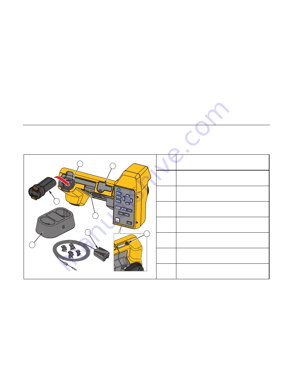
Table 3 shows the location of the battery and 
interfaces. 


Table 3. Bottom Panel 

6

7

3

2

1

4

5


hwj002.eps 

Item Description 


Smart Battery Port 


Lithium-ion Smart Battery 


Anchor for Neck Strap 


SD Memory Card Slot 

 Tripod 

Mount 


2-Bay Battery Charging Base 


AC Power Adapter with Universal Adapter 

Summary of Contents for TiX520

Page 1: ... 2015 Fluke Corporation All rights reserved Specifications are subject to change without notice All product names are trademarks of their respective companies TiX520 TiX560 Expert Series Thermal Imager Users Manual ...

Page 2: ...ice center to obtain return authorization information then send the product to that service center with a description of the difficulty postage and insurance prepaid FOB Destination Fluke assumes no risk for damage in transit Following warranty repair the product will be returned to Buyer transportation prepaid FOB Destination If Fluke determines that failure was caused by neglect misuse contamina...

Page 3: ... Radio Frequency Data 3 Accessories 5 Before You Start 6 Battery 7 Two Bay Battery Charger Base 7 On Imager AC Power Socket 7 Optional 12 V Vehicle Charger 8 Features and Controls 10 Power On and Off 11 Focus 11 Image Capture Button 12 Control Buttons 12 Touch Screen 15 How to Use the Menus 16 Neck Strap 16 Image Capture 17 ...

Page 4: ...easurement Menu 20 Range 20 Level Span 21 Emissivity Adjustment 22 Background Reflected Background Temperature Compensation 23 Transmission Transmittance Adjustment 24 Spot Temperatures 24 Center Box 24 Markers 25 Image Menu 26 Palette 26 IR Fusion Technology 27 Color Alarms 27 Display Graphics Presentation 28 Logo 29 Distance 29 Camera Menu 29 Auto Focus 29 Backlight 30 Video 30 HDMI 31 Auto Capt...

Page 5: ... 34 File Format 34 Auto Off 35 Localization 35 Image Storage 36 Advanced Settings 36 Fluke Connect Wireless System 38 Fluke Connect App 38 Fluke Connect Tools 38 Remote Control 39 Maintenance 39 How to Clean the Case 40 Battery Care 40 General Specifications 41 Detailed Specifications 43 ...

Page 6: ...TiX520 TiX560 Users Manual iv ...

Page 7: ...v List of Tables Table Title Page 1 Symbols 4 2 Accessories 5 3 Bottom Panel 9 4 Features 10 5 Controls 13 6 Touch Targets 15 7 Level and Span Settings 22 8 Palettes 26 ...

Page 8: ...TiX520 TiX560 Users Manual vi ...

Page 9: ...vii List of Figures Figure Title Page 1 Laser Warning 2 2 Add On Lens Installation 6 3 Adjustable Neck Strap 16 ...

Page 10: ...TiX520 TiX560 Users Manual viii ...

Page 11: ... on Imager requires Bluetooth headset IR PhotoNotes Fluke Connect WIFI connectivity Streaming video Remote control and operation Image Presentation Standard Palettes Red Grayscale Inverted Grayscale High Contrast Amber Inverted Amber Hot Metal Ironbow Ultra Contrast Palettes Blue Red Ultra Grayscale Ultra Inverted Grayscale Ultra High Contrast Ultra Amber Ultra Inverted Amber Ultra Hot Metal Ultra...

Page 12: ...afety Information A Warning identifies conditions and procedures that are dangerous to the user A Caution identifies conditions and procedures that can cause damage to the Product or the equipment under test Warning To prevent eye damage and personal injury Do not look into the laser Do not point the laser directly at persons or animals or indirectly off reflective surfaces Do not open the Product...

Page 13: ...ratures Reflective objects result in lower than actual temperature measurements These objects pose a burn hazard Do not use the Product around explosive gas vapor or in damp or wet environments Operation in Extreme Conditions Storage and or continual operation of the Imager in extreme ambient temperature conditions can result in temporary interruption of operation If this occurs let the Imager sta...

Page 14: ...n This Product contains a lithium ion battery Do not mix with the solid waste stream Spent batteries should be disposed of by a qualified recycler or hazardous materials handler per local regulations Contact your authorized Fluke Service Center for recycling information This product complies with the WEEE Directive 2002 96 EC marking requirements The affixed label indicates that you must not disca...

Page 15: ...ARGER 12 V Vehicle Charger Adapter 3039779 FLUKE TIX5xx Neck Strap 4574715 FLUKE TIX5xx Hand Strap 4574703 FLK Bluetooth Bluetooth Headset 4603258 FLK HDMI Cable HDMI Cable 4388596 FLK HDMI Adapter HDMI Adapter 4613365 BOOK ITP Introduction to Thermography Principles 3413459 FLK LENS TELE2 2X Telephoto Infrared Lens 4335377 FLK LENS WIDE2 Wide Angle Infrared Lens 4335361 FLK LENS 4XTELE2 4X Teleph...

Page 16: ...n Smart Batteries Hard Carrying Case USB to PC Cable HDMI Video Cable Removable Memory Card Hard Transport Case Adjustable Hand Strap left hand or right hand use Adjustable Neck Strap Quick Reference Guide Users Manual SmartView Software on USB Drive Warranty Registration Card Fluke recommends the removable memory card that is supplied with the Imager or available from Fluke Fluke does not warrant...

Page 17: ... the options that follow Two Bay Battery Charger Base 1 Connect the ac power supply to the ac wall outlet and connect the dc output to the charger base 2 Put one or two smart batteries into bays of charger base 3 Charge batteries until charge indicators show full 4 Remove smart batteries and disconnect the power supply when batteries are fully charged On Imager AC Power Socket 1 Connect the ac pow...

Page 18: ... process Keep the Imager attached to the charger until the icon shows a full charge If you remove the Imager from the charger before a full charge shows it may have a reduced run time Note When the battery is connected to ac power or the unit is in video mode the Sleep Mode Auto Off feature is disabled automatically Optional 12 V Vehicle Charger 1 Connect the 12 V adapter into the 12 V accessory s...

Page 19: ...ocation of the battery and interfaces Table 3 Bottom Panel 6 7 3 2 1 4 5 hwj002 eps Item Description Smart Battery Port Lithium ion Smart Battery Anchor for Neck Strap SD Memory Card Slot Tripod Mount 2 Bay Battery Charging Base AC Power Adapter with Universal Adapter ...

Page 20: ...ER 1 12 9 10 2 3 4 6 5 8 7 11 hwj004 eps Item Description Infrared Camera Lens Focus Control Laser Distance Finder Visual Camera and Lens Laser Distance Finder Button Image Capture Button Hand Strap Anchor AC Adapter Charger Input Terminal USB to PC Cable Connection USB Accessory Connection HDMI Video Connection LED Light ...

Page 21: ...ls of the detector Without correct focus the thermal image can be blurry and the radiometric data may be inaccurate Out of focus infrared images are frequently unusable or of little value The Fluke LaserSharp Auto Focus System uses a precision adjusted and aligned laser pointer to indicate the area of focus To focus with the LaserSharp Auto Focus System depress the large black button see Table 4 A...

Page 22: ... localization selection Time and date settings Emissivity selection Reflected background temperature compensation Transmission correction User selectable hot spot and cold spot and center point on the image Expand contract measurement box with MIN AVG MAX Color alarms User selectable backlight setting Graphic information display selectable Laser distance display In general push to set the change a...

Page 23: ...and their actions Table 5 Controls 11 6 7 9 10 8 5 4 3 1 2 hwj001 eps Item Button Description LCD Touch Screen Power On Off Function Buttons F1 F2 F3 Cursor Buttons Go to IR Fusion Menu Manual Auto Level and Span Go to internal Image Memory LED Light Zoom In Zoom Out Fluke Connect Rescale ...

Page 24: ... Light illuminates darker work areas Push to turn on and turn off the LED light at any time during operation Zoom TiX520 Push to set the zoom function between no zoom 2x and 4x TiX560 Push to set the zoom function between no zoom 2x 4x and 8x Fluke Connect The Imager supports the Fluke Connect Wireless System may not be available in all regions Push to go directly to the wireless setup menu More i...

Page 25: ...ers or select functions and options touch a target on the display with a finger The touch screen has a backlight for work in dimly lit spaces To change the backlight intensity see Camera Menu Table 6 shows the location of each touch target Table 6 Touch Targets 1 2 3 4 6 5 hwj012 eps Item Description Go to Temperature Unit Adjustment menu Manual Auto Toggle Go to Palette menu Go to Measurement men...

Page 26: ...n correspond to the buttons You can use the buttons or the touch screen interchangeably for these functions Push to open the primary menu Push to cycle through the secondary menus Each secondary menu lists an options menu Push to cycle through the options The primary secondary and option menus close 10 seconds after the last push of a function button The option selection menu stays open until you ...

Page 27: ...e visible digital images of various objects text or other information that is related to the analysis and reporting of an infrared image Examples of possible annotations include motor name plates printed information or warning signs larger views of the environment or room and related equipment or objects Up to five images can be captured with the visible image that is stored in addition to the ali...

Page 28: ... i icon identifies each file that has a voice annotation The voice audio recording replays through a Bluetooth headset or when you use SmartView software To play back 1 Do the steps in the Review Image Files section on page 33 to see the image on the display 2 Push 3 Push to set Audio 4 Push to listen to the audio 5 Push again to pause the audio Edit Captured Infrared Image Before and after you sa...

Page 29: ...ager senses the infrared energy from the surface of the object and uses this data to calculate an estimated temperature value Many common objects and materials such as painted metal wood water skin and cloth are very good at radiating energy and it is easy to get relatively accurate measurements For surfaces that are good at radiating energy high emissivity the emissivity factor is 90 or 0 90 This...

Page 30: ...so available for flexibility away from your PC or in the field Menus The menus are the access points for thermal image display camera features memory setup and settings for date time language units file format and Imager information Measurement Menu The Measurement Menu has settings for the calculation and display of radiometric temperature measurement data related to the thermal images These sett...

Page 31: ...lower settings at the same time Temperature Level for Manual Operation Mode When put into manual ranging the level setting moves the thermal span up or down within the total temperature range In the live manual mode the arrow buttons are always available to adjust the level and span To set the level 1 Push to move the range to a higher temperature level 2 Push to move the range to a lower temperat...

Page 32: ... the display shows the thermal span increasing or decreasing in size Emissivity Adjustment The correct emissivity values are important for the Imager to make the most accurate temperature measurement calculations Emissivity of a surface can have a large effect on the apparent temperatures that the Imager observes Understanding the emissivity of the surface being inspected can but not always allow ...

Page 33: ...cated when any value not in the standard emissivity table is selected Select by Table To select from a list of common materials 1 Go to Measurement Emissivity Select Table 2 Push to highlight the material 3 Push to select the material Background Reflected Background Temperature Compensation Compensation for reflected background temperature is set in the Background tab Very hot objects or very cold...

Page 34: ... transmission correction as τ xx Spot Temperatures The Spot Temperatures are floating HI and LO temperature indicators that move on the display as the temperature measurements of the image fluctuate To turn on off the hot and cold spot indicators 1 Go to Measurement Spot Temp 2 Push to highlight ON or OFF 3 Select Hot or Cold 4 Push or to set the new value Center Box The Center Box feature is an a...

Page 35: ...e live view Markers Up to three adjustable fixed temperature spot markers are available on the display You can use these markers to highlight a region before you save the image The marker selection is set as All Off One Marker Two Markers or Three Markers To set a Marker 1 Go to Measurement Markers 2 Push the to highlight the function between All OFF One Marker Two Markers and Three Markers 3 Push...

Page 36: ...tation of colors that allow for best presentation of detail The Ultra Contrast Palettes offer a weighted presentation of colors These palettes work best in situations with high thermal contrast for extra color contrast between the high temperatures and low temperatures Table 8 Palettes Standard Palettes Ultra Contrast Palettes Grayscale Grayscale Ultra Grayscale Inverted Grayscale Inverted Ultra B...

Page 37: ...d SmartView Mobile Software when you use the is2 file format To set the IR Fusion technology mode 1 Go to Measurement Image IR Fusion 2 Push to highlight an option 3 Push to set the new option TiX560 The TiX560 model has an adjustable IR Level Push to open the scroll bar that adjusts the IR Fusion mode Use it to infinitely adjust the picture from Full IR mode to Full Visible mode Color Alarms The ...

Page 38: ...erature dew point color alarm 1 Go to Image Color Alarm Set Low Alarm 2 Push to adjust the temperature setting 3 Push or set a new value Outside Inside Alarm If you set values for the high temperature color alarm and a low temperature color alarm the Imager will have the options for inside or outside color alarms To set an outside inside color alarm 1 Go to Image Color Alarm Outside or Inside 2 Pu...

Page 39: ...nt 1 Point the Imager at the target 2 Push the Laser Distance Finder button 3 Locate the red laser dot on the target 4 Release the Laser Distance Finder button The distance measurement shows on the bottom of the display The measurement shows as when not able to take a measurement If this is the case steady the Imager and retake the measurement Or use a tripod The Imager will show an error message ...

Page 40: ... The backlight level control is set to low medium and high To set the backlight 1 Go to Camera Backlight 2 Push to highlight high medium or low 3 Push to set a new value Video The Imager can record infrared and IR Fusion to the SD card or internal memory in is3 or avi format To record 1 Go to Camera Video 2 Push to select Video Audio or Video ONLY A Bluetooth headset is required and the radio must...

Page 41: ...the Auto Capture feature 1 Go to Camera Auto Capture 2 Push Start Capture to start the capture sequence In the Auto Capture sub menu you will see these options Start Capture Executes the Auto Capture settings in camera memory Interval Set the hours minutes and seconds between individual image capture events Push to select the number of hours minutes or seconds as an interval between images Image C...

Page 42: ...e 3 Type the registration information into the web page The server checks if the radio can be enabled for this address If yes a passphrase is provided to paste into SmartView SmartView validates that the passphrase is correct and then enables the radio in the Imager Bluetooth Bluetooth is available to connect a device such as a wireless headset When on shows on the display upper left corner WiFi H...

Page 43: ...hows to indicate any additional items saved with the infrared image or IR Fusion technology image IR PhotoNotes photos Voice annotation Review Image Files To view stored images on the memory card 1 Go to Memory 2 Push to highlight the preview image of the file for review 3 Push to review the file Edit Image Files You can make all the same adjustments to a file in memory as you can in real time inc...

Page 44: ...ption 3 Push to set the option Images saved in the is2 file format have the consolidation of all data into a single file and are more flexible for analysis and modification in the included SmartView software This file format consolidates the infrared image radiometric temperature data visible image voice annotation and photos from the IR PhotoNotes photo annotation system into one location For sit...

Page 45: ...zation Date Time Language Decimal Separator Date The date can be displayed in one of two formats MM DD YY or DD MM YY To set the date 1 Go to Settings Date 2 Push to highlight the date format 3 Push to set a new format 4 Push to highlight Set Date 5 Push to open the Set Date menu 6 Push to select highlight day month or year 7 Push to change the settings 8 Push to set the date and exit the menu Tim...

Page 46: ...Image Storage The storage setting allows you to choose to save images to the internal memory micro SD memory card or USB flash memory 1 Go to Settings Image Storage 2 Push or to change the setting 3 Push to select the new storage setting Advanced Settings Filename Prefix The default filename starts with IR_ You have the option to change this prefix to a different 3 character name with the touch sc...

Page 47: ...ation screen Adjust Parallax With the use of optional add on lenses you can fine tune the parallax adjustment to precisely align the image 1 Go to Settings Advanced Adjust Parallax 2 Follow the on screen prompts to adjust Image Enhancement Image enhancement is available on the TiX560 with the Image Sharpening and SuperResolution modes Image Sharpening uses post processing of the image to remove bl...

Page 48: ...oad from the Apple App Store and Google play How to access Fluke Connect 1 Insert the Fluke Connect Wireless SD Card into the Imager 2 Power on the Imager 3 On your smartphone go to Settings Wi Fi 4 Select the Wi Fi network that begins with Fluke 5 Go to the Fluke Connect App and select Thermal Imager from the list You are now able to take images on the Imager 6 Push the Image Capture button on th...

Page 49: ...rtView software or the Fluke Connect app To set up 1 Attach the included USB cable to the USB port on the imager 2 Connect the other end to a USB port on a PC 3 In SmartView software choose Remote Display from the drop down menu to begin live video streaming on the PC To remotely control and show the Imager s display 1 If not installed install the latest version of SmartView software on your PC 2 ...

Page 50: ...p cells and battery packs clean and dry Clean dirty connectors with a dry clean cloth Caution To prevent damage do not expose Product to heat sources or high temperature environments such as an unattended vehicle in the sun To get the best performance from the lithium ion battery use the guidelines that follow Do not store the Imager on the charger for more than 24 hours as reduced battery life ma...

Page 51: ...ilable for free download at www fluke com Power Batteries 2 Lithium ion rechargeable smart battery packs with 5 segment LED display to show charge level Battery Life 3 hours continuous use for each battery pack assumes 50 brightness of LCD Battery Charge Time 2 5 hours to full charge AC Battery Charge Ti SBC3B Two Bay Battery Charger 110 V ac to 220 V ac 50 60 Hz included or in Imager charging AC ...

Page 52: ... the levels required by CISPR 11 can occur when the equipment is connected to a test object Korea KCC Class A Equipment Industrial Broadcasting Communication Equipment Class A Equipment meets requirements for industrial electromagnetic wave equipment and the seller or user should take notice of it This equipment is intended for use in business environments and not to be used in homes USA FCC 47 CF...

Page 53: ...ity correction 1 to 100 On screen reflected background temperature compensation yes On screen transmission correction 1 to 100 Imaging Performance Image Capture Frequency 9 Hz or 60 Hz refresh rate Detector Type 320 X 240 Focal Plane Array uncooled microbolometer Thermal Sensitivity NETD TiX520 50 mK 40 mK with Filter Mode TiX560 45 mK 30 mK with Filter Mode Total pixels 76 800 Infrared spectral b...

Page 54: ...4 19 mRad 15 cm 6 in Optional 4X Telephoto Go to www fluke com for more information Optional 25 micron macro Focus Mechanism LaserSharp Auto Focus System all models Advanced Manual Focus all models Level and Span Smooth Auto Scaling and Manual scaling of level and span Fast auto setting switching between manual and auto modes Fast auto rescale in manual mode Minimum Span in manual mode 2 0 C 3 6 F...

Page 55: ...recording time minimum of ten minutes 30 Hz requires class 10 micro SD Radiometric Viewable on Imager and with SmartView software in proprietary is3 format Supports voice recording in addition to captured video Video functions to include stop rewind fast forward pause play Maximum recording time minimum of ten minutes 30 Hz Storage Medium Micro SD Memory Card Includes 4 GB memory card to store at ...

Page 56: ...TiX520 TiX560 Users Manual 46 ...

Reviews: