


268XA
Service Manual
2-22
AC Volts Measurement Circuitry.
AC-coupled voltage inputs are scaled by an ac buffer (A3U29), converted to dc by a true
RMS ac-to-dc converter (A3U26), filtered by an active ac volt filter, then sent to the
Stallion IC, the Buffer Amplifier, and the A/D Conversion Circuitry (see Table 2-6). The
HI input is switched to the ac buffer through dc blocking capacitor A3C80. The LO input
is sensed through A3L52, A3R146, A3K27, A3R119, and S33 and S37. The gain or
attenuation of the ac buffer is selected by A3U30’s ACR1-ACR4 outputs. 0 V turns
JFETS A3Q10 to A3Q16 ON, while –5 V (V ac) turns the JFETS OFF. Only one line at a
time is set at 0 V.
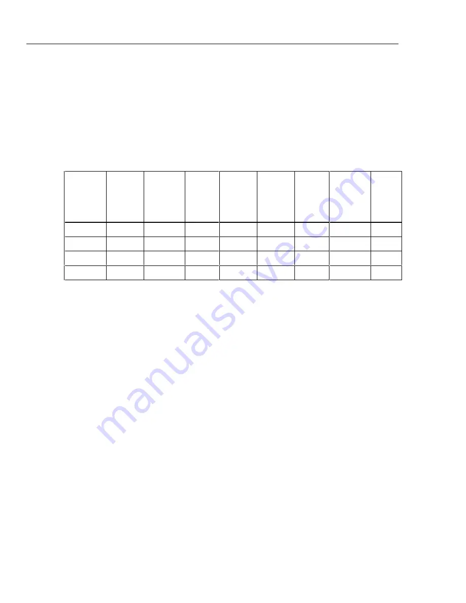
Table 2-6. Measurement Matrix for AC Volts
AC Volt
Range
Gain of AC
Volts
Buffer
Amplifier
Full-Scale
Output of
AC Volts
Buffer
Amplifier
Full-Scale
Output of
RMS
Converter
Full-Scale
Input to
Stallion
(dc volts)
Full-Scale
Output of
Stallion
(dc volts)
Gain of
DC Buffer
Amplifier
Full-Scale
DC Volts
Input to
Multislope
A/D
Buffer
Range
Control
Signal
300 mV
2.5
0.75 V rms
0.75 V
300 mV
300 mV
10
3 V
BR3
3 V
0.25
0.75 V rms
0.75 V
300 mV
300 mV
10
3 V
BR3
30 V
0.025
0.75 V rms
0.75 V
300 mV
300 mV
10
3 V
BR3
150/300 V
0.0025
0.75 V rms
0.75 V
300 mV
300 mV
10
3 V
BR3
The ac voltage input signal is routed through and scaled by the buffer to obtain a full
scale buffer output of 0.75 V rms at A3U29-6. A3R120 and A3C76 provide high
frequency compensation on the 300 mV range. The output of the buffer is ac coupled to
the input of the ac-to-dc RMS converter. The output of the RMS converter (0.75 V dc) is
divided by 2.5 by A3Z2 and sent to the acv filter. The filtered output is sent to pin 31
(ACFO) of the Stallion chip via S41. Full scale input to Stallion is 300 mV dc. Figure 2-8
shows a simplified signal path for the 3 V ac range.
Summary of Contents for 2680A
Page 6: ......
Page 12: ...268XA Service Manual vi ...
Page 18: ...268XA Service Manual 1 2 ...
Page 48: ...268XA Service Manual 1 32 ...
Page 96: ...268XA Service Manual 2 48 ...
Page 98: ...268XA Service Manual 3 2 ...
Page 106: ...268XA Service Manual 3 10 ...
Page 132: ...268XA Service Manual 5 2 ...
Page 194: ...268XA Service Manual 6 48 ...
Page 196: ...268XA Service Manual 7 2 ...
Page 204: ...268XA Service Manual 7 10 268X FINAL ASSEMBLY alg105f eps Figure 7 1 268XA Final Assembly ...
Page 207: ...Replaceable Parts Parts Lists 7 7 13 2680A DIO alg100f eps Figure 7 3 DIO Module ...
Page 209: ...Replaceable Parts Parts Lists 7 7 15 2680A FAI alg102f eps Figure 7 4 FAI Module ...
Page 211: ...Replaceable Parts Parts Lists 7 7 17 2680A PAI alg103f eps Figure 7 5 PAI Module ...
Page 214: ...268XA Service Manual 8 2 ...
Page 215: ...8 3 8 Schematic Diagrams Figure 8 1 Backplane PCA 2680A 4001 ...
Page 216: ...268XA Service Manual 8 4 Figure 8 1 Backplane PCA cont 2680A 1001 ...
Page 217: ...8 5 8 Schematic Diagrams Figure 8 2 Controller System Power PCA 2680A 4004 ...
Page 223: ...8 11 8 Schematic Diagrams Figure 8 3 Digital I O PCA 2680A 4006 ...
Page 224: ...268XA Service Manual 8 12 Figure 8 3 Digital I O PCA cont 2680A 1006 1 of 3 ...
Page 225: ...8 13 8 Schematic Diagrams Figure 8 3 Digital I O PCA cont 2680A 1006 2 of 3 ...
Page 226: ...268XA Service Manual 8 14 Figure 8 3 Digital I O PCA cont 2680A 1006 3 of 3 ...
Page 227: ...8 15 8 Schematic Diagrams Figure 8 4 Backplane Extender PCA 2680A 4009 ...
Page 228: ...268XA Service Manual 8 16 Figure 8 4 Backplane Extender PCA cont 2680A 1009 ...
Page 229: ...8 17 8 Schematic Diagrams Figure 8 5 Extender PCA 2680A 4010 ...
Page 230: ...268XA Service Manual 8 18 Figure 8 5 Extender PCA cont 2680A 3010 ...
Page 231: ...8 19 8 Schematic Diagrams Figure 8 6 A D Supply Assembly 2680A 4031 ...
Page 232: ...268XA Service Manual 8 20 Figure 8 6 A D Supply Assembly cont 2680 1031 ...
Page 233: ...8 21 8 Schematic Diagrams Figure 8 7 PCMCIA PCA 2680A 4041 ...
Page 234: ...268XA Service Manual 8 22 Figure 8 7 PCMCIA PCA cont 2686 1041 ...
Page 235: ...8 23 8 Schematic Diagrams Figure 8 8 Output PCA 2680A 4062 ...
Page 236: ...268XA Service Manual 8 24 Figure 8 8 Output PCA cont 2680A 1062 ...
Page 237: ...8 25 8 Schematic Diagrams Figure 8 9 A D PFE PCA 2640A 4003 ...
Page 238: ...268XA Service Manual 8 26 Figure 8 9 A D PFE PCA cont 1 of 6 ...
Page 239: ...8 27 8 Schematic Diagrams Figure 8 9 A D PFE PCA cont 2 of 6 ...
Page 240: ...268XA Service Manual 8 28 Figure 8 9 A D PFE PCA cont 2640A 1003 3 of 6 ...
Page 241: ...8 29 8 Schematic Diagrams Figure 8 9 A D PFE PCA cont 2640A 1003 4 of 6 ...
Page 242: ...268XA Service Manual 8 30 Figure 8 9 A D PFE PCA cont 2640A 1003 5 of 6 ...
Page 243: ...8 31 8 Schematic Diagrams Figure 8 9 A D PFE PCA cont 2640A 1003 6 of 6 ...
Page 244: ...268XA Service Manual 8 32 Figure 8 10 A D FFE PCA 2645A 4003 ...
Page 245: ...8 33 8 Schematic Diagrams Figure 8 10 A D FFE PCA cont 2645A 1003 1 of 6 ...
Page 246: ...268XA Service Manual 8 34 Figure 8 10 A D FFE PCA cont 2645A 1003 2 of 6 ...
Page 247: ...8 35 8 Schematic Diagrams Figure 8 10 A D FFE PCA cont 2645A 1003 3 of 6 ...
Page 248: ...268XA Service Manual 8 36 Figure 8 10 A D FFE PCA cont 2645A 1003 4 of 6 ...
Page 249: ...8 37 8 Schematic Diagrams Figure 8 10 A D FFE PCA cont 2645A 1003 5 of 6 ...
Page 250: ...268XA Service Manual 8 38 Figure 8 10 A D FFE PCA cont 700p29_topress zip 2645A 1003 6 of 6 ...
Page 251: ...8 39 8 Schematic Diagrams Figure 8 11 Analog Input Connector PCA 2620A 4004A ...
Page 252: ...268XA Service Manual 8 40 2620A 1004 Figure 8 11 Analog Input Connector PCA cont ...
Page 253: ...8 41 8 Schematic Diagrams Figure 8 12 Display PCA 1 of 1 ...
Page 254: ...268XA Service Manual 8 42 Figure 8 12 Display PCA cont 1 of 1 ...


