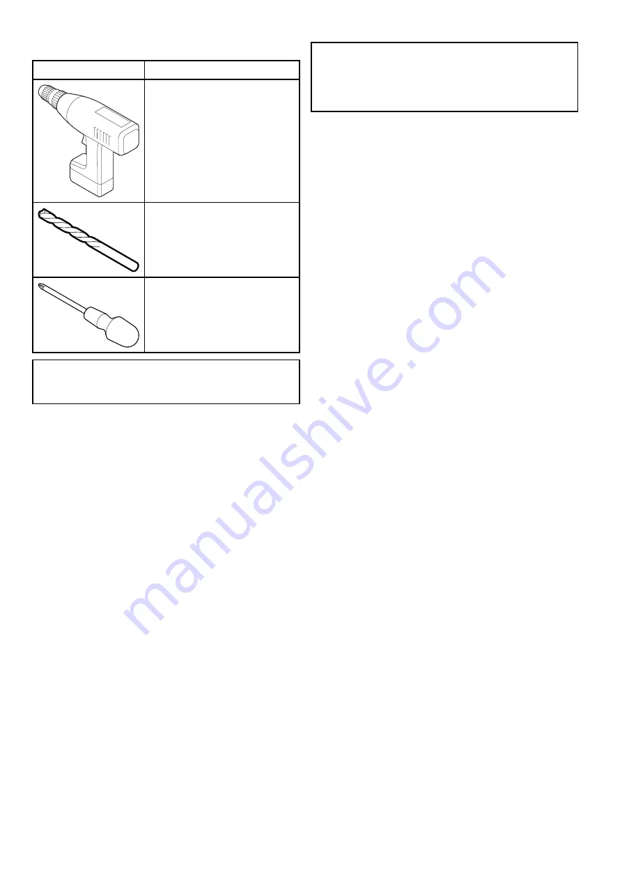
3.4 Tools required
Product installation requires the following tools:
Item
Description
Power drill
Drill bit of appropriate size*
Pozi drive screwdriver
Note:
* The appropriate drill bit size is dependent
on the thickness and material of the mounting
surface.
3.5 Typical systems
Note:
For
information
on
how
to
connect
the
product,
refer
to
the
Chapter
4
Cables
and
connections
section.
For
information
on
available
cables
and
accessories,
refer
to
the
Chapter
11
Spares
and
accessories
section.
•
Basic
multifunction
display
(MFD)
system:
You
can
connect
the
product
directly
to
a
multifunction
display
using
the
supplied
RJ45
coupler,
and
an
additional
adaptor
cable
(refer
to
the
4.5
Network
connection
section
for
details).
If
you
are
connecting
the
product
to
an
a,
c,
e,
or
eS
Series
MFD,
the
camera
requires
a
separate
power
source,
either
connecting
directly
to
your
vessel’s
12
V
dc
power
supply,
or
using
a
Power
over
Ethernet
(PoE)
injector
(refer
to
the
4.4
Power
connection
section
for
details).
If
you
are
connecting
the
product
to
a
gS
Series
MFD,
the
camera
can
be
supplied
PoE
by
the
display,
provided
the
display
has
the
necessary
remaining
PoE
allocation.
Refer
to
the
gS
Series
installation
and
operation
instructions
for
details
on
PoE
allocation,
and
also
to
the
4.4
Power
connection
section.
•
Multiple
camera
system:
You
can
use
a
Raymarine
network
switch
to
connect
multiple
cameras
to
a
single
MFD.
Each
camera
requires
a
separate
power
supply,
unless
the
switch
is
capable
of
providing
PoE,
or
if
the
camera
is
connected
directly
to
a
gS
Series
MFD
supplying
PoE.
Refer
to
the
4.5
Network
connection
and
4.4
Power
connection
sections
for
details.
•
PC
/
laptop
system:
You
can
connect
the
product
to
a
PC
or
laptop
computer,
directly
via
the
computer’s
Ethernet
connector,
or
indirectly
via
a
Raymarine
network
switch.
Refer
to
the
4.5
Network
connection
section
for
details.
When
connected
to
a
PC
or
laptop
computer,
you
can
access
the
product’s
built-in
web
interface.
CAM200IP / CAM210IP


