background image

• Mozilla Firefox

• Apple Safari

• Microsoft Internet Explorer 7.0 or later, 32–bit

version (using ActiveX)

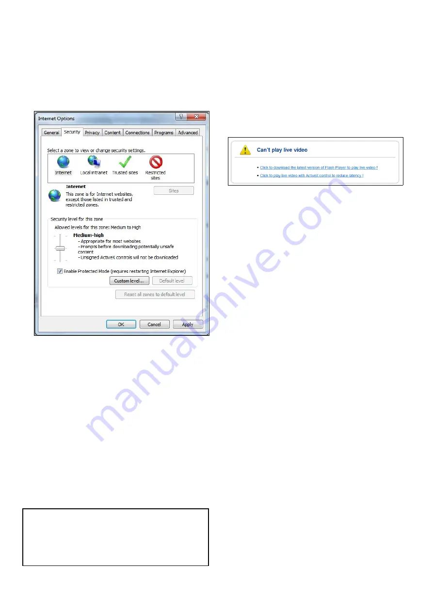
Setting up Internet Explorer

If you are using Microsoft Internet Explorer then you
may need to change the internet settings.
1. Click

Tools > Internet Options > Security

.

2. Click

Custom Level

.

3. Under

Download unsigned ActiveX controls

,

click

Prompt

(recommended) or

Enable

.

4. Click

OK

and then click

OK

again.

Accessing using a web browser

1. Open your web browser from a web-enabled

device connected to the same network as the IP
camera.

2. Enter your camera’s IP address in the

browser’s address bar in the following format:

http://192.168.1.100:80

and press

Return

.

3. Enter the username and password for the camera

and click

Login

.

The main screen for the camera web interface is
displayed. From here you can configure and view
the camera feed.

Note:

If you do not see the camera feed, make

sure your computer has the latest version of Adobe
Flash Player (Chrome, Firefox Internet Explorer
and Safari) or ActiveX (Internet Explorer only)
installed. After installing restart your browser and
reconnect to the camera.

Internet Explorer - ActiveX and Flash Player

The ActiveX plug-in may provide smoother video
performance than Flash Player.
1. If your computer has Flash Player installed:

i.

Open the web interface.

ii. Click the message above the video window.
iii. Click inside the video area and select

Install

this Add-on for all users on this computer

.

iv. Follow the onscreen prompts.

2. If your computer does not have Flash Player

installed you will be prompted to select if you
would like to use ActiveX or Flash Player:

Click to play live video with ActiveX control
to reduce latency (Recommended)

— Uses

the ActiveX plug-in to connect to the camera.
To install the plug-in, click on the video area,
and select

Install this add-on for all users

on this computer

.

Click to download the latest version of Flash
Player to play live video

— Opens a link to

download Flash Player from Adobe’s website.
After completing the installation, restart your
browser and open the web interface.

CAM200IP / CAM210IP

Summary of Contents for Raymarine CAM200IP

Page 1: ...INSTALLATION INSTRUCTIONS CAM200IP CAM210IP...

Page 2: ...mes or company names referenced herein are used for identification only and are the property of their respective owners This product is protected by patents design patents patents pending or design pa...

Page 3: ...uct ensure the power source is adequately protected by means of a suitably rated fuse or automatic circuit breaker Warning Ensure all equipment has isolated power supply This product features an isola...

Page 4: ...ot cut or extended unless doing so is detailed in the installation manual Note Where constraints on the installation prevent any of the above recommendations always ensure the maximum possible separat...

Page 5: ...this document was correct at the time it was produced However Raymarine cannot accept liability for any inaccuracies or omissions it may contain In addition our policy of continuous product improvemen...

Page 6: ...Chapter 2 Document and product information Chapter contents 2 1 Document information 2 2 Product overview Document and product information...

Page 7: ...n product variant and date of manufacture All images are provided for illustration purposes only Product documentation The following documentation is applicable to your product Description Part number...

Page 8: ...44 minutes of record time per 1 GB of available storage space CAM210IP The CAM210IP is an Infrared illuminated I2 bullet IP camera with both day and night vision In conjunction with a compatible mult...

Page 9: ...s 3 1 Installation checklist 3 2 Compatible multifunction displays 3 3 Parts supplied 3 4 Tools required 3 5 Typical systems 3 6 Warnings and cautions 3 7 General location requirements 3 8 Pan and til...

Page 10: ...ential part of planning any installation It is also useful for any future additions or maintenance of the system The diagram should include Location of all components Connectors cable types routes and...

Page 11: ...on available network hardware and cables refer to Chapter 11 Spares and accessories CAM210IP The following items are supplied with your product Item Description Quantity IP camera Includes a 1 m 39 4...

Page 12: ...or using a Power over Ethernet PoE injector refer to the 4 4 Power connection section for details If you are connecting the product to a gS Series MFD the camera can be supplied PoE by the display pro...

Page 13: ...o transmitters receivers Magnetic compass refer to the Compass safe distance section in this document for advice on maintaining a suitable distance between this product and any compasses on your vesse...

Page 14: ...pan angle can be adjusted up to 360 the camera s tilt angle can be adjusted up to 90 Note Pan and tilt angle adjustment is a mechanical procedure performed by physically adjusting the camera s positi...

Page 15: ...Chapter 4 Cables and connections Chapter contents 4 1 General cabling guidance 4 2 Connections overview 4 3 Power options 4 4 Power connection 4 5 Network connection Cables and connections...

Page 16: ...bulkhead or deckhead use a suitable watertight feed through Do NOT run cables near to engines or fluorescent lights Always route data cables as far away as possible from other equipment and cables hig...

Page 17: ...s product must be powered using ONE of the following methods 1 PoE Power over Ethernet Either Direct connection to a Raymarine gS Series MFD only one cable is required to carry both data and power sig...

Page 18: ...using a PoE injector 12 v dc D13090 1 2 5 6 3 4 1 1 MFD 2 IP camera 3 PoE injector R32141 not supplied 4 Camera s ethernet connection 5 RayNet to SeaTalkhs adaptor cable not supplied 6 Camera s power...

Page 19: ...y via a suitably rated fuse or breaker The power cable supplied with your product may NOT include a separate drain wire If this is the case only the power cable s red and black wires need to be connec...

Page 20: ...ine fuse to the positive wire of your product s power connection Warning Grounding not required This product is fully insulated and does NOT require separate grounding 4 5 Network connection The unit...

Page 21: ...and cables refer to Chapter 11 Spares and accessories Network switch connection Multiple camera s can be networked together using an network switch or router D13095 1 1 2 3 4 5 6 12 v dc 12 v dc Item...

Page 22: ...Chapter 5 Mounting Chapter contents 5 1 Mounting the unit Mounting...

Page 23: ...d holes in the mounting surface 7 Secure the base in position using the screws and nylon washers provided ensuring that the camera s cables sit in the camera base s cable channel or feed through the c...

Page 24: ...Chapter 6 Operation Chapter contents 6 1 Operation instructions 6 2 Web browser interface 6 3 Reverse video and video flip 6 4 Resetting the camera to factory defaults Operation...

Page 25: ...s is assigned automatically You can find out what IP address your camera has been assigned using IP scanner software supplied UPnP Note You may need to change your network settings to connect to a PC...

Page 26: ...ble click a camera icon to open the web interface in your default browser 3 Enter the username and password for the camera and click Login Finding the camera s IP address using IP Scanner software To...

Page 27: ...h Player Chrome Firefox Internet Explorer and Safari or ActiveX Internet Explorer only installed After installing restart your browser and reconnect to the camera Internet Explorer ActiveX and Flash P...

Page 28: ...eras Mirror For cameras facing aft V flip For forward facing cameras where the camera image appears upside down Rotate For cameras facing aft where the camera image appears upside down 6 4 Resetting t...

Page 29: ...Chapter 7 Maintenance Chapter contents 7 1 Routine checks 7 2 Unit cleaning instructions Maintenance...

Page 30: ...gh voltage Adjustments require specialized service procedures and tools only available to qualified service technicians There are no user serviceable parts or adjustments The operator should never rem...

Page 31: ...Chapter 8 System checks and troubleshooting Chapter contents 8 1 Troubleshooting 8 2 LED status 8 3 IP camera troubleshooting 8 4 Resetting the camera System checks and troubleshooting...

Page 32: ...e problems with the operation of your product this section will help you to diagnose and correct problems in order to restore normal operation If after referring to this section you are still having p...

Page 33: ...Ensure that the MFD and camera are physically connected to the same network Ensure that the MFD is running the latest version of LightHouse software Try power cycling the IP camera whilst leaving you...

Page 34: ...y reset However in the event that a factory reset is required the camera s built in web interface must be used The camera s web interface can be accessed when connected to a web enabled device such as...

Page 35: ...Chapter 9 Technical support Chapter contents 9 1 Raymarine product support and servicing Technical support...

Page 36: ...these services through the Raymarine website telephone and e mail Product information If you need to request service or support please have the following information to hand Product name Product iden...

Page 37: ...Chapter 10 Technical specification Chapter contents 10 1 Technical specification Technical specification...

Page 38: ...JPEG Resolutions 1280 x 720 default supporting up to 1920 x 1080 FHD Video streaming Supports multi streaming with H 264 MJPEG Frame Rate H 264 30fps 1920 x 1080p MJPEG 30fps VGA resolution Bit Rate...

Page 39: ...ns 1280 x 720 default supporting up to 1920 x 1080 FHD Video streaming Supports multi streaming with H 264 MJPEG Frame Rate H 264 30fps 1920 x 1080p MJPEG 30fps VGA resolution Bit Rate Control Dual st...

Page 40: ...er 11 Spares and accessories Chapter contents 11 1 Network hardware 11 2 RayNet to RJ45 adapter cables 11 3 Network cable connector types 11 4 RayNet to RayNet cables and connectors Spares and accesso...

Page 41: ...es the connection of RJ45 SeaTalkhs devices to a HS5 RayNet network switch in conjunction with suitable adapter cables Enables 2 RJ45 SeaTalkhs cables to be connected together to extend the length of...

Page 42: ...watertight fit Directly connect a Raymarine radar scanner with an RJ45 SeaTalkhs male cable to a RayNet network switch e g HS5 or LightHouse MFD 1 3 Adapter cable with a RayNet male plug on one end a...

Page 43: ...11 3 Network cable connector types There are 2 types of network cable connector RayNet and RJ45 SeaTalkhs RJ45 SeaTalkhs connector RayNet connector CAM200IP CAM210IP...

Page 44: ...o the twist lock on RayNet cables enabling you to pull the cables through conduits and other obstacles 5 3 RayNet to RayNet right angle coupler adapter Suitable for connecting RayNet cables at 90 righ...

Reviews: