background image

427-0033-00-12 Version 110

February 2019

22

This document does not contain any export-controlled information.

Basic Operation and Configuration

LAN Settings > IEEE 802.1X Security

The 802.1x standard is designed to enhance the security of local area networks. The standard 

provides an authentication framework, allowing a user to be authenticated by a central authority. The 

F

-

Series ID supports authentication using Transport Layer Security (TLS) protocol.

Notes

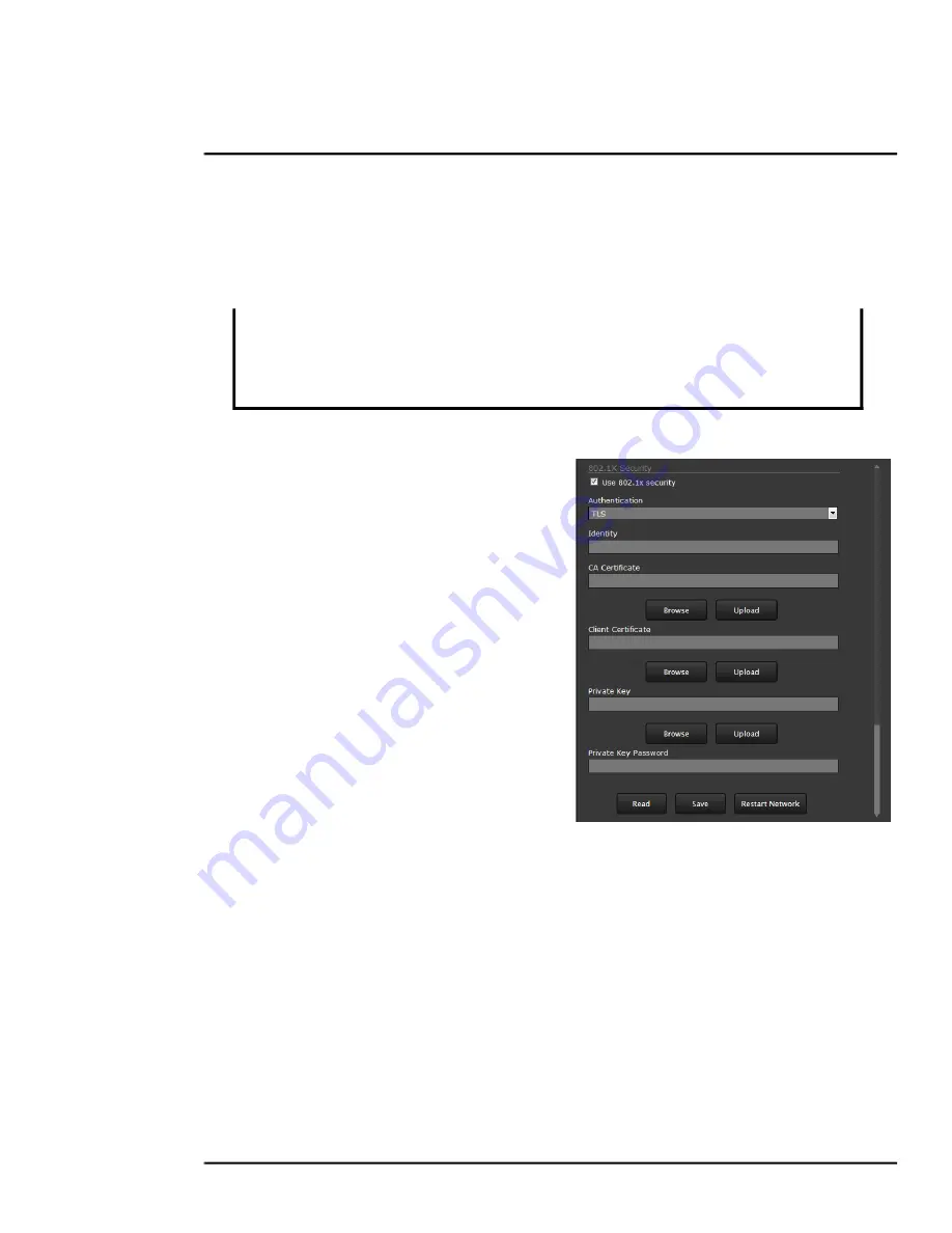
Configure IEEE 802.1x authentication using TLS

Step 1

On the

 LAN Settings

 page, scroll down 

to 

802.1X Security

.

Step 2

Select the 

Use 802.1x security


checkbox.

Step 3

From the 

Authentication

 drop-down 

menu, select 

TLS

.

Step 4

In the 

Identity

 text box, enter the name 

associated with the client certificate.

Step 5

If uploading a PKCS #8 certificate file, 

use the 

Browse

 and 

Upload

 buttons to 

upload the associated 

CA Certificate


from the server provided by the network 

administrator.

If uploading a PKCS #12 certificate file, 

you do not need to upload a CA 

Certificate. 

Step 6

Use the 

Browse

 and 

Upload

 buttons to upload the 

Client Certificate

 from the server 

provided by the network administrator.

Step 7

Using the 

Browse

 and 

Upload

 buttons, upload the 

Private Key

 and 

Private Key 

Password

 associated with the identity. The 

Private Key Password

 field can be left blank 

if a password is not required.

If uploading a PKCS #8 file, the private key must be a valid PKCS #8 file.
If uploading a PKCS #12 file, the private key must be a valid PKCS #12 file.

Certificates and keys must be in PEM format. Common file extensions for TLS files in PEM format 

are:

For certificate and public key files: 

*.crt, *.cer, *.cert, *.pem

For private key files:

 *.key

The camera must be connected to a switch or other device on the network that supports 

IEEE 802.1x.

The camera also supports TLS for communication with clients outside the LAN, such as 

web browsers. For information about enabling and configuring TLS for communication 

outside the LAN, see 

Services > TLS Config, pg. 25

.

Summary of Contents for F-606-ID-N

Page 1: ...427 0033 00 12 Version 110 February 2019 This document does not contain any export controlled information Installation Manual F Series ID...

Page 2: ...unications Operation of this equipment in a residential area is likely to cause harmful interference in which case the user will be required to correct the interference at his own expense Shielded cab...

Page 3: ...able Gland Sealing 9 1 3 11 Cable Glands and Spare Parts Kit 10 1 3 12 Cable Gland Seal Inserts 10 1 4 Camera Connections 11 1 4 1 Connecting power 11 1 4 2 Video Connection 12 1 4 3 GPIO Alarm Connec...

Page 4: ...controlled information Advanced Configuration 3 1 Setup Menu 33 3 1 1 Temperature Page 33 3 1 2 Input Output IO Page 34 3 1 3 Video Setup 34 3 1 4 Thermal Image Setup IR Page 36 3 1 5 Video Analytics...

Page 5: ...tructure petrochemical facilities nuclear facilities commercial campuses and residential neighborhoods The FLIR Thermal Fence gives you instant automated threat detection and visual threat assessment...

Page 6: ...ac or 21 30 Vdc The F Series ID camera produces both analog video and digital IP video output Analog video will require a connection to a video monitor or an analog video matrix switch An Ethernet con...

Page 7: ...edestal Mount Kit 500 0463 00 The pedestal mount is designed to support loads up to 40 pounds 18 kg The mount features a fully adjustable swivel head allowing 360 degree horizontal and 75 degree verti...

Page 8: ...e to wind The tilt angle is the angle between vertical and the center of the camera field of view 1 3 6 Bench Testing Connect the power analog video and Ethernet connections and confirm that the video...

Page 9: ...ted between the case and the back cover as shown If the grounding wire is temporarily disconnected during the installation it must be reconnected to ensure proper grounding of the camera 1 3 10 Cable...

Page 10: ...NPT cable glands each with a three hole gland seal insert Cables may be between 0 23 to 0 29 OD Up to five cables may be needed Plugs are required for any insert hole s not used If non standard cable...

Page 11: ...remove power to the Back Cover Chassis GND 16 AWG Shielded 16 AWG Shielded 24 VAC DC 24 VAC DC Earth Ground 24 VAC DC 24 VAC DC Earth Ground Local Ground 24 VAC DC 24 VAC DC Male BNC Ethernet Analog...

Page 12: ...of the camera housing and connected to the nearest earth grounding point Note 1 4 2 Video Connection The analog video connection on the back of the camera is a BNC connector The camera also provides...

Page 13: ...nt channels of streaming H 264 or M JPEG Thermal AGC Modes Optimized Video Analytics AGC Mode and manual controls for Brightness ITT Mean gamma Contrast Max Gain Sharpness DDE Gain and AGC Filter Vide...

Page 14: ...0 95 relative Vibration IEC 60068 2 27 Mechanical Shock MIL STD 810F Transportation De Icing MIL STD 810F Method 521 1 De Icing of 3 6mm model dependent Compliance and Certifications EN 61000 6 4 200...

Page 15: ...ch camera to be configured with a different static IP address On the other hand many of the configuration parameters will remain unchanged from the factory default settings 2 2 Camera Bench Test The c...

Page 16: ...pen the camera s web server Login page in a web browser or point your web browser to the camera s IP address Step 6 Using the web browser configure the camera settings such as camera date time and oth...

Page 17: ...ge and enter the camera IP address The login screen with a picture of the camera will appear Enter admin for the User Name and admin for the Password and click Log in 2 2 3 Live Video Page The Live Vi...

Page 18: ...on from this page on hand For information about the factory configuration of the camera refer to the Maintenance Product Info Identification web page requires Admin login Log out Use this button to di...

Page 19: ...the button When the mouse is positioned over the video window a snapshot button is shown in the upper right corner of the video image The snapshot button will save an image as a jpg file to the select...

Page 20: ...res The basic camera configuration steps are accessed through the Maintenance Server menu using the menus on the left side of the page The LAN Settings Services and Security Options selections are des...

Page 21: ...iguration steps are accessed through the Maintenance menu using the Server page When a user logs in as expert or admin the Server page is available The LAN Settings Date and Time Server Status and Sec...

Page 22: ...rver provided by the network administrator If uploading a PKCS 12 certificate file you do not need to upload a CA Certificate Step 6 Use the Browse and Upload buttons to upload the Client Certificate...

Page 23: ...if it is public or located on a different network Stop the server The server must be stopped before date and time settings can be saved Click the Save button at the bottom of the page After the settin...

Page 24: ...Systems page with mail server information and then click Save Using the admin login check that Messaging is enabled Refer to Maintenance Sensor Summary Page pg 56 Services Notification Lists Use this...

Page 25: ...certificate signed by a third party Certificates and keys must be in PEM format Common file extensions for TLS files in PEM format are For certificate and public key files crt cer cert pem For privat...

Page 26: ...point a confirmation appears To upload a self signed or third party CA signed certificate Step 1 For Method select Upload Certificates Step 2 If you are uploading a self signed certificate under Uploa...

Page 27: ...her to redirect HTTP requests to HTTPS Step 3 Click Save Step 4 Click Reboot The camera reboots After the camera reboots TLS is enabled Server Status The Server Status page provides an indication of t...

Page 28: ...ping the server When the server is stopped and the page is refreshed the status will show Server Stopped and the Start button will be enabled Click on the Start button to restart the server and when t...

Page 29: ...understanding of the differences between thermal and daylight cameras can help with getting the best performance from the thermal camera Both thermal and daylight cameras have detectors pixels that de...

Page 30: ...ir com support center training No video Check the video connection at the camera and at the display If the connectors appear to be properly connected but the camera still does not produce an image ens...

Page 31: ...rsonal Firewall may ask for permission to allow the video player to communicate on the network Select the check boxes domain private public that are appropriate for the network If necessary test to ma...

Page 32: ...ommend intentionally viewing the sun but looking at the sun will not permanently damage the sensor The thermal imaging camera often provides a considerable advantage over a visible camera in a back li...

Page 33: ...It is a good idea to make a backup of the existing configuration file prior to making changes and another backup once the changes are finalized If necessary the camera can be restored to its original...

Page 34: ...page shows a summary of the status of all GPIO signals 3 1 3 Video Setup Video By default two video streams are enabled for the camera Video 0 and Video 1 Both video streams are available for viewing...

Page 35: ...the default parameters provide high quality full frame rate video streams with reasonable bandwidth usage In general for most installations it will not be necessary to modify the default parameters H...

Page 36: ...val results in higher bandwidth more full frames sent and better video quality A higher I Frame Interval number means fewer I frames are sent and therefore results in possibly lower bandwidth and poss...

Page 37: ...ers some convenient options When Custom is selected a handle is shown in the center of the screen Drag the handle to set the size of the ROI box Drag the ROI box over the portion of the scene that wil...

Page 38: ...g in a more gradual transition Range 0 to 100 Misc Each Colorization Look Up Table LUT provides a different display of the various detected levels of thermal energy as either colors or gray scale valu...

Page 39: ...he analytics detect and classify objects as expected Auto Calibration If the scene is well ordered and without random motion from things such as trees shrubs or small animals and access is limited to...

Page 40: ...Have a person walk around at the bottom of the area Select the blue box at the bottom of the screen and drag to fit the subject Click Save Step 4 Set the far size aspect ratio for a person Have a pers...

Page 41: ...tracking line with each detection box All Boxes every detected motion is shown with a box around it Classified Boxes detected motion classified as vehicle human or object of interest is shown with a b...

Page 42: ...the video to create the first corner of the area Continue adding corners then select Finish to complete the area This is motion detection masking not privacy masking The video image will still be see...

Page 43: ...arm condition has occurred 3 2 Maintenance Menu The following sections describe more advanced camera configuration options that require the admin login For the configuration changes in the remainder o...

Page 44: ...firewalls and so on As an additional security consideration it is possible to restrict access to the camera by remote clients by setting the Allow Anonymous Clients to No and then enter IP addresses f...

Page 45: ...tions pg 28 to add an allowed IP address to the list in the Restrict Web Configuration section File Transfer The camera can send a captured image when an alarm occurs as well as storing the image loca...

Page 46: ...gured with a VMS Remote interface with ONVIF 2 0 parameters Profile S Several types of third party Video Management Systems VMS are supported by FLIR IP cameras Because these systems tend to evolve an...

Page 47: ...ain to restart the server Click Accept at the prompt The status will show Server Running Link Cameras on trk 101 P Tracker Link the PTZ camera and the F Series ID from the trk 101 P web interface Step...

Page 48: ...her camera with Automatic PTZ tracking Step 7 Follow the procedure described in the FLIR ioi HTML Edition Units User Guide to synchronize the F Series ID to the PTZ camera Step 8 When finished return...

Page 49: ...nel Input Output 2 The Label setting can be changed to reflect more specific alarm information which can then appear in VMS systems such as FLIR Latitude The GPIO Name determines the circuit point for...

Page 50: ...e streams are available for viewing from a client program such as FLIR Latitude a stand alone video player or a third party VMS including ONVIF systems Caution To modify parameters that affect a parti...

Page 51: ...bility of IP packets to traverse network boundaries A value of 1 restricts the stream to the same subnet Greater values allow increasing access between networks The video streaming is done using a pro...

Page 52: ...by adding additional rules for example one action could capture an image and another could generate an output If a message is to be sent from the camera as a result of an alarm it is necessary to defi...

Page 53: ...e configured to Send a Notification Capture an Image or Arm Disarm Analytics If more than one action is needed it is necessary to configure multiple rules Examples of these actions are provided below...

Page 54: ...JPEG image Radiometric a special type of JPEG with temperature data is not available on the F Series ID camera Scroll to the bottom of the page and click on the Save button to save settings Changes w...

Page 55: ...attach a snapshot from the camera to the email In Attach Image File All Non Radiometric is selected for the type of image After making any changes you must scroll to the bottom of the page and click...

Page 56: ...when an alarm occurs and turns off when the alarm is cleared or the Output Reset Interval is reached see Devices Menu GPIO pg 48 If Unbound the output turns on when an alarm occurs and remains on unti...

Page 57: ...3 2 2 Files Menu The administrative actions for accessing updating and transferring files are accessed through the Files menu on the left side of the page Selected actions from the Firmware Configurat...

Page 58: ...restore the camera to its factory settings This file can not be modified or deleted so it is always available Use the Backup button to make a backup of the final settings This will make a backup copy...

Page 59: ...gging parameters Scroll down and select the Download button under Field Support Log to download a zip file to the computer for field service evaluation Media Browser The Media Browser page shows all o...

Page 60: ...the Media Browser page Select Edit to select and delete individual images or all images Any time the camera is rebooted or the power removed the media directory will be emptied 3 2 3 Product Info Menu...

Page 61: ...2019 61 This document does not contain any export controlled information Advanced Configuration Click on the Save button to save the settings The changes will not take effect until the server is stopp...

Page 62: ...IR Systems Inc 6769 Hollister Ave Goleta CA 93117 USA Corporate Headquarters FLIR Systems Inc 27700 SW Parkway Ave Wilsonville OR 97070 USA Support https www flir com support center support hq This do...

Reviews: