background image

Flint & Walling © Copyright 2018. All rights reserved.

  8 

VFD

Minimum Generator rating

VS/TVS15

4 .8kW

VS/TVS20

8 .0kW

VS/TVS30

 10 .0kW

TVS50

15 .7 KW

Note: If additional loads are being supplied by the generator, 

the generator manufacture should be contacted for correct 

sizing . When the controller is being supplied power by a 

generator the Powered by Generator option should be set 

to YES in the advanced features menu to minimize possible 

damage to the drive .

Drive Configuration

When sized correctly, the drive controller package systems 

are fully programmed and are ready to go right out of the box 

without need for additional configuration . There are several 

parameters that can be changed:  

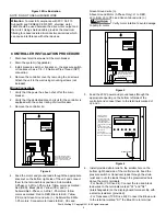
Figure 9 Display and Keypad

 Capacitors inside the drive controller 

can still hold a lethal voltage even after power has been 

removed. Allow 10 minutes for dangerous internal voltage 

to discharge before making changes to input power or 

motor connections.

By pressing and holding the EDIT & ENTER buttons down 

together for 5 seconds, you enter into the program menu . 

Using the UP & DOWN buttons, you can scroll through the 

menus and view the current settings . To make a change to 

a parameter press the EDIT button followed by the UP and 

DOWN buttons to set or choose the new value . Once the 

new values is set, press the ENTER button to accept the new 

value or the ESCAPE button to discard the change . Once 

you are done viewing and changing the parameters press 

ESCAPE to return to the home screen .
For further information to change these parameters, please 

call Technical Support at 800-742-5044 . 

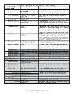
KEY:

APPLIES ONLY TO TRANSDUCER

APPLIES ONLY TO PRESSURE SWITCH

APPLIES TO EITHER OPTION

(1) Control Choice

Switch or Transducer

At initial power-up, the drive will detect what control devise is 

attached and will automatically set the control choice .  If a switch or 

transducer is not hooked up, the drive will default to Switch as it's 

control choice .

Set Transducer Range 

(Only for Transducer 

Control)

50-300 PSI 

Default 100 PSI

Programs the drive to the range of the pressure transducer that is 

attached . (Drive ships with 100PSI transducer .)

Set Pressure Set Point 

(Only for Transducer 

Control)

15 - (Max Transducer range - 5) 

Default 50

Target system pressure . 

Set Draw Down PSI 

(Only for Transducer 

Control)

2-15 PSI 

Default 5 PSI

Sets the amount that the system pressure has to drop below the set 

point while the drive is in standby before the drive will restart the 

motor .

Access menu options by pressing and holding edit and enter for 3 seconds .

Menu Option

Action

Notes

Summary of Contents for Commander Pro

Page 1: ... pressure Key features of the drive controller include Can use either a pressure switch no snap action or a 4 20mA transducer as the pressure control At initial power up the controller detects whether a switch or transducer is connected and automatically sets the control choice Constant water pressure with a wide range of settings 30 80 psi Note The maximum obtainable system pressure is limited by...

Page 2: ... prevent mechanical damage which could produce serious electrical shock and or equipment failure Pump is designed to pump cold ground water that is free of air or gases Decreased pump performance and life expectancy can occur if the ground water is not cold 86ºF 30ºC or contains air or gases Pump and controls must be securely and adequately grounded as specified in section 250 43 item A of the U S...

Page 3: ... in equipment and property damage as well as possible injury Always install a pressure relief valve capable of passing full pump flow at 100 PSI Install the pressure relief valve between the pump and pressure tank PRESSURE SETTING GUIDE System Pressure at Pressure Sensor Pressure Tank Setting PSI 2 psi 25 18 30 21 35 25 40 28 45 32 50 factory set 35 55 39 60 42 65 46 70 49 75 53 80 56 Pressure Rel...

Page 4: ...ve access to 230V electrical supply and to the submersible motor wiring 6 Do not expose the drive to water spray greater than 30 from vertical Note Installations that require larger than 6 AWG wire will require an external junction box Run 6 AWG from the drive to the junction box and make external connections to the appropriately sized wire with wire nuts WIRING SIZING CHART Maximum Wire Lengths C...

Page 5: ...D Black BLK Yellow YEL and W Submersible 3 Phase or 3 Wire 1 Ph motors follow colors as marked Red to RED Black to BLK Yellow YEL and Green Ground wire W Submersible 2 Wire 1 Ph motors Connect motor leads to BLK YEL and Green Ground wire W Above Ground Motor 3 Phase Only L1 to RED L2 to BLK L3 to YEL and Green Ground wire W Verify motor rotation to avoid damage to pump motor L1 L2 RED BLK YEL IN O...

Page 6: ...ightening the thumbscrew finger tight START UP OPERATION Apply power to the controller The display should briefly show Please Wait Initializing and then read Press Enter to Begin Set Up Pressing ENTER button will begin taking you through the quick set up menu where you can select Pump type Submersible or Above Ground Motor type Three Phase 3W Single Phase if option is available Maximum Motor Curre...

Page 7: ...imer low level switch etc can be used to trip the drive with an External Fault trip For this connection to work properly the Alarm in Relay contact condition setting in the Advanced Features Menu must be set to match the switch position to activate the drive Example An irrigation timer closes a contact to single the drive to run the Alarm In Relay setting should be set to NC Normal Closed for the ...

Page 8: ...eter press the EDIT button followed by the UP and DOWN buttons to set or choose the new value Once the new values is set press the ENTER button to accept the new value or the ESCAPE button to discard the change Once you are done viewing and changing the parameters press ESCAPE to return to the home screen For further information to change these parameters please call Technical Support at 800 742 5...

Page 9: ...w the BM current the drive will ramp up for the BM duration regardless of switch state to create an overpressure drawdown Set bump mode duration Sets the time duration of the ramp up for a bump in PSI 5 to 2 0 sec Default 0 5 sec By increasing this duration time the amount of overpressure for drawdown can be increased Caution Increasing this time too much has the potential of creating a high over ...

Page 10: ...n or normally closed Default NO The state of the relay changes when the drive trips Typically not for use in most residential applications Powered by Generator No Yes Default No Set the drive circuitry to expect power delivered from a gas driven generator Depending upon application a 5 10 pressure drop of can be experienced when the drive is running the pump motor at full speed Ramp up sensitivity...

Page 11: ...uit Replace transducer Deadhead Switch control Pump running against a closed discharge Make sure that there is not a valve closed or obstruction between the pump and pressure switch Damaged or clogged pressure switch Check continuity across switch contacts without wire connected and replace and or clean pressure port Deadhead sensitivity incorrect Adjust deadhead sensitivity in Underload Protectio...

Page 12: ...ith higher flow rating if head requirement is still satisfied Temperature in the controller is too high If the controller s heat exchanger becomes too hot the controller will reduce the output frequency to the motor to lower the power consumption Make sure there is at least 4 inches of room around the controller for movement of air Avoid direct sunlight Reduce ambient temperature below 104 F 40 C ...

Reviews: