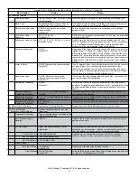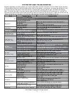
Flint & Walling © Copyright 2018. All rights reserved.
5
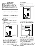
Figure 3 Wire Illustration
NOTE: DO NOT USE ALUMINUM WIRE .
A
ttention
: To meet full compliance with FCC Part 15
Subpart B and CENELEC EN 55011, shielded motor
cable should be used between the drive motor output and
the motor . Using shielded cable provides the maximum
filtering to reduce radiated & conductive emissions which
can cause interference with other devices .
CONTROLLER INSTALLATION PROCEDURE
1 . Disconnect electrical power at the main breaker
2 . Drain the system (if applicable)
3 . Install pressure switch or transducer - the pressure switch
or transducer has a 1/4 - 18 National Pipe Thread (NPT)
connection .
4 . Remove the controller cover by removing the lid screws .
Attach the unit to the wall using mounting screws (not
included) .
Wiring Connections
1 . Verify that the power has been shut off at the main
breaker .
2 . Verify that the dedicated branch circuit for the controller is
equipped with the correct rating of circuit breaker .
3 . Remove the controller lid .
L1 L2
IN OUT + -
S1 S2
ALARMS FAN SENSOR
IL1791
RED
BLK
YEL
Feed motor and ground leads
through appropriate knockout
and connect to RED, BLK, YEL
and
W
on right hand terminal
block.
Figure 4
4 . Feed the motor and ground leads thought the appropriate
knockout on the bottom right side of the unit and connect
them to the terminal block positions . Submersible
3-Phase or 3-Wire 1-Ph motors: follow colors as marked:
Red (RED), Black (BLK), Yellow (YEL) and (
W
) .
Submersible 3-Phase or 3-Wire 1-Ph motors: follow
colors as marked: Red to RED, Black to BLK, Yellow
(YEL) and Green Ground wire (
W
) . Submersible 2-Wire
1-Ph motors: Connect motor leads to BLK, YEL and
Green Ground wire (
W
) .
Above Ground Motor (3-Phase Only): L1 to RED,
L2 to BLK, L3 to YEL and Green Ground wire (
W
)
Verify motor rotation to avoid damage
to pump & motor .
L1 L2
RED BLK YEL
IN OUT + -
S1 S2
ALARMS FAN SENSOR
IL1790
Feed 230V power and ground
leads through appropriate
knockout and connect to
L1, L2 and
W
on left hand
terminal block
Figure 5
5 . Feed the 230V power and ground leads through the
appropriate opening on the bottom left side of the
controller and connect them to the terminals marked L1,
L2 and
W
.
S2
IL1792
S1
Feed the pressure
switch/transducer
wire through the strain
relief (bottom right) and
route cable through
grommeted hole above
the motor power terminal
block .
Connect to S1 and S2
terminals on display board
terminal strip .
For transducer,
Brown wire connects to S1
Blue wire connects to S2
Grommeted hole
IN OUT + -
ALARMS FAN SENSOR
Figure 6
6 . Install provided strain relief in the smaller hole on the
bottom right hand side of the controller unit . Feed the
pressure switch or transducer leads through the strain
relief and route the leads through the grommetted hole
above the motor terminals .
- For Switch (VS Drive Kit): Connect the red and black
lead wires to the terminals marked "S1" and "S2"
(interchangeable) on the display board terminal strip with
a small screwdriver (provided) .
- For Transducer (TVS Drive Kit): Connect the Brown wire
to the terminal marked "S1" the Blue Wire to terminal


