background image

AP BIO

Technical Description

400/500/1000/2400

FG-DC_10523-GB_AP Bio_IOM-R0-12/2020 • Subject to modifications

13

4.2

Functional description

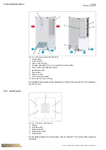
4.2.1 AP BIO air purifier (Model 2400)

Fig. 4-4

Functional overview

1: Indoor air inlet
2: Control panel
3: Indicator light
4: Fan
5: Air outlets
6: Second HEPA H14 filtration barrier
7: First ISO ePM1 55% (F7) filtration barrier

The control panel (2) used to adjust the air flow rate of the unit.

The electrically driven fan (4) creates a constant negative pressure in the air column.

The air flows through the indoor air inlet (1) and further through the ISO ePM1 55% 
(F7) filtration barrier (7). In this step 55% of particles and microbes are captured.

A second HEPA H14 filtration barrier (6), which is also impregnated with the 100% 
natural AirFend

TM 

bio-decontaminating solution in powder form, deactivates viruses 

and bacteria.

The clean air flows out through the air outlets (5) where traps are present to reduce 
noise levels.

The indicator light (3) indicates a filter change when the loading conditions are 
reached.

Summary of Contents for AP BIO 1000

Page 1: ...AP BIO 400 500 1000 2400 AIR PURIFIER INSTALLATION OPERATION AND MAINTENANCE MANUAL ...

Page 2: ...es 9 3 11 Spare parts 10 3 12 Disposal 10 3 13 Selection and qualification of personnel 10 4 Technical Description 11 4 1 Unit description 11 4 2 Functional description 13 4 3 Technical data AP BIO 14 4 4 Operating limits 14 4 5 Spare parts 15 5 Shipping and storage 16 5 1 Delivery 16 5 2 Transport 16 5 3 Storage 17 6 Assembly 18 6 1 Erecting the unit 18 7 Commissioning and operation 19 7 1 Overvi...

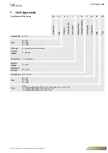
Page 3: ...ccessories Product line Size Type Product line AP BIO Size 04 400 05 500 10 1000 24 2400 Filter set B biological anti virus bacteria Control system S standard Fan control C constant flow Design frame W white Additional features 00 without Accessories ZAP AP BIO Size 04 400 05 500 10 1000 24 2400 Type Filters FS biological filter ISO ePM1 55 F7 HEPA filter H14 set for 1 unit FP pre filter ISO ePM1 ...

Page 4: ...d in the packaged content Unit according to designation on the unit identification plate Operation manual including all information on the supplied unit Possible accessories and special equipment only if ordered Consider supplied operation and installation manuals for accessories supplied separately Notice Use only provided order related documentation for commissioning maintenance and servicing of...

Page 5: ... at all times Anyone who works with or on the unit must read and observe this operation manual The operation manual is intended for use by fitting and installation companies building services engineers technical personnel or trained persons as well as electrical specialists 3 2 Scope of the operation manual This operation manual provides information about the following Assembly disassembly Use and...

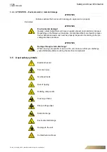
Page 6: ...jury Indicates a hazardous situation which can result in minor or moderate injury if the safety instruction is not followed Example Electrocution through hazardous voltage will lead to death or serious injury Disconnect the unit from the power supply and ensure the power cannot be switched back on Ensure the unit is voltage free and isolated earth and short circuit the unit cover or shield off nei...

Page 7: ... processes Depending on the filtered out materials contaminated filters are therefore classi fied as hazardous waste and must be properly disposed of according to the pre vailing directives and laws ATTENTION Damage through static discharge While carrying out adjustment work on the unit make sure that you discharge yourself statically before touching the electrical components Electrical hazard Per...

Page 8: ...l kinds of work Please comply with the installation and shipping instructions for FläktGroup units Observe the pre commissioning requirements Always make sure that the FläktGroup unit is accessible only to authorized and trained technical personnel If necessary use appropriate equipment to keep unauthorized persons away from the unit Electrocution through hazardous voltage will lead to death or se...

Page 9: ...onsidered improper The manufacturer supplier is not liable for damage arising from improper use The user alone bears the risk 3 9 Safety standards and regulations During installation electrical connection commissioning repairs and maintenance of the AP BIO air purifiers ensure to meet the applicable safety regulations standards and generally accepted technical rules DIN EN 60335 1 ed 3 Household a...

Page 10: ...ng supply materials must be disposed of according to material type in an environmentally friendly manner please refer to chapter 10 2 Disposal 3 13 Selection and qualification of personnel Ensure that every person working on the unit has read and understood this entire operation manual especially the chapter on safety It is too late to do this after work has already begun All skilled staff must be...

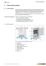
Page 11: ...nd viruses AP BIO air purifiers are fully completed at the factory and are subjected to a test oper ation so they are easy and quick to install Directives and regulations Units meet the following directives and standards Directive on Machinery 2006 42 EC Low Voltage Directive LVD 2014 35 EU Electromagnetic Compatibility EMC 2014 30 EU Certified Quality Management System ISO 9001 4 1 1 General over...

Page 12: ... with integrated switch 6 Identification plate 7 Rear casters 8 Clean air outlet 9 Front caster with brake 10 Door lock for access with key For installed components on the individual unit refer to the data sheets or the quotation text for the unit 4 1 2 Control panel Fig 4 3 Overview control panel 1 Display 2 Increase button 3 Decrease button 4 Mode setting button 5 On Off button For the data disp...

Page 13: ... the unit The electrically driven fan 4 creates a constant negative pressure in the air column The air flows through the indoor air inlet 1 and further through the ISO ePM1 55 F7 filtration barrier 7 In this step 55 of particles and microbes are captured A second HEPA H14 filtration barrier 6 which is also impregnated with the 100 natural AirFendTM bio decontaminating solution in powder form deact...

Page 14: ...elocity 0 90 m s 0 90 m s 0 90 m s 0 50 m s Dimensions LxWxH 435x435x820mm incl wheels 435x435x1225mm incl wheels 740x435x1245mm incl wheels 690x640x1625mm incl wheels Weight 25 kg 32 kg 58 kg 89 kg Operating voltage 230 V AC 50 Hz 230 V AC 50 Hz 230 V AC 50 Hz 230 V AC 50 Hz Max power consumption 180 W 180 W 350 W 1360 W Sound pressure level LPA at max airflow at a distance of 1m from the air pur...

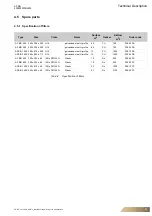
Page 15: ...50 ZAP 04 FB AP BIO 500 305 x 305 x 292 H14 galvanized steel U profile 6 5 PU 750 ZAP 05 FB AP BIO 1000 305 x 610 x 292 H14 galvanized steel U profile 13 PU 1500 ZAP 10 FB AP BIO 2400 450 x 850 x 117 H14 galvanized steel U profile 14 PU 1400 ZAP 24 FB AP BIO 400 305 x 305 x 48 ISO ePM1 55 Plastic 1 6 No 500 ZAP 04 FP AP BIO 500 305 x 305 x 48 ISO ePM1 55 Plastic 1 6 No 500 ZAP 05 FP AP BIO 1000 30...

Page 16: ...ove the unit carefully without fast irregular movements Do not move the unit in case of strong wind conditions Always set the unit down gently without bumping it If required engage a specialist company to ship the unit Notice Missing parts or claims of shipping damage can only be reported to the transport insurance if the damage has been confirmed by the delivering carrier Notice We recommend keep...

Page 17: ...o the feet of the unit that are long enough for the lifting ropes and anti slip devices to be attached For the dimensioning of the pipes please refer to the figure in the corresponding section To avoid damage make sure that the hoist ropes cannot rub against the unit For your own safety wear gloves and safety footwear when lifting or shipping the unit 5 3 Storage Allowable storage conditions allow...

Page 18: ...op of the unit are not blocked otherwise operation performance and noise levels will be affected Roll the unit to the desired position and apply the brake on the front casters AP BIO 2400 and AP BIO 1000 Connect the power supply If necessary use an extension cord compatible with the electrical power of the unit see identification plate Note on mounting and installing the unit Here you will find in...

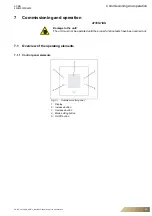
Page 19: ...ommissioning and operation 7 1 Overview of the operating elements 7 1 1 Control panel elements Fig 7 1 Overview control panel 1 Display 2 Increase button 3 Decrease button 4 Mode setting button 5 On Off button ATTENTION Damage to the unit The unit must not be operated until the proper function tests have been carried out ...

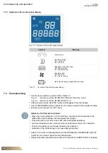
Page 20: ... the INCREASE or DECREASE button to adjust the air volume setpoint to the desired value Repeat the above activation procedure when the AirFend HEPA14 filter is replaced Symbol Meaning Constant flow On Off status light Off Unit is off On Unit is on Regulation mode status light Off Manual mode On Automatic mode Fan status light Off Fan is off On Fan is running Alarm light indicating clogged filter a...

Page 21: ...button To cut off the power supply to the unit set the power switch to position OFF O Refer to Fig 4 1 General overview AP BIO 400 500 and 1000 Pos 5 and Fig 4 2 General overview AP BIO 2400 Pos 5 7 4 Settings In automatic mode the airflow rate of the unit is indicated in m3 h the setpoint remains within the minimum and maximum values specified in table 4 1 on page 14 In automatic mode when the IN...

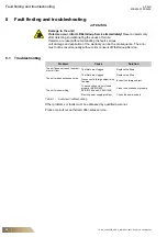
Page 22: ...e cause of failure If alarms are reset without eliminating the fault serious unit damage and expiration of the warranty can be the consequence The error must not be reset manually without prior consent of FläktGroup Service Problem Cause Solution The unit does not reach the maxi mum air flow The filters are clogged Replace the filters The unit makes excessive noise The filters are clogged Replace ...

Page 23: ...d ensure the power cannot be switched back on Ensure the unit is voltage free and isolated earth and short circuit the unit cover or shield off neighboring live components Warning of rotating fan When working on the unit or in case of damage to the components the running fan will lead to serious injury Warning of contaminated filter surfaces When working on the unit or in case of damage to the com...

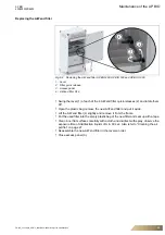
Page 24: ...side Slide out the used pre filter very carefully put it into the empty plastic bag of the new filter and seal up with a tape Clean inner flat surfaces carefully with a cloth and disinfect with spray observe the exposure time of disinfection liquids of min 30 sec Also refer to Cleaning the air purifier on page 27 Slide in the new filter and make sure it is pushed it in all the way until it touches...

Page 25: ...d filter quick releases 2 and rotate them 90 Open the plastic bag remove the new AirFend filter and put it aside Lift the AirFend filter 4 slightly and remove it from the frame Put the used filter into the empty plastic bag of the new filter and seal up with a tape Clean inner flat surfaces carefully with a cloth and disinfect with spray observe the exposure time of disinfection liquids of min 30 ...

Page 26: ...Filter ISO ePM1 55 F7 H14 Swing the lever 1 of each of the 4 AirFend filter quick releases 2 and rotate them 90 Open the plastic bags remove the new filters and put them aside Extract the used filters 3 from the unit one at a time put these into the empty plastic bags of the new filters and seal up with a tape Clean inner flat surfaces carefully with a cloth and disinfect with spray observe the ex...

Page 27: ...Hygiene Refer to the above sources list for details and consider the specified concentration and exposure time Use the following cleaning agents e g BODE Microbak or DESOMED Desotop For correct concentration refer to the data sheet provided by the manufacturer and or select a non visible small surface to test the solution there beforehand Using alcohol containing agents is not allowed due to risk ...

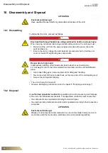
Page 28: ... unit Electrocution through hazardous voltage will lead to death or serious injury When carrying out decommissioning and dismantling work on the unit you must Disconnect the unit from the power supply and ensure the power cannot be switched back on Ensure the unit is voltage free and isolated ground and short circuit the unit cover or shield off neighboring live components Danger due to high loads...

Page 29: ...ve ErP 2018 Ecodesign Remplissent les exigences de la Directive 2006 42 CE relative aux machines Remplissent d autre part les exigences applicables des Directives CE suivantes x 2014 30 CE CEM 2009 125 CE Ecodesign Règlement UE n º 327 2011 x 2009 125 CE Ecodesign Règlement UE n º 1253 2014 x 1999 5 CE RTTE appareils radioélectriques et équipements terminaux de télécommunications Sont en conformit...

Page 30: ...Notes AP BIO 400 500 1000 2400 30 FG DC_10523 GB_AP Bio_IOM R0 12 2020 Subject to modifications ...

Page 31: ...AP BIO Notes 400 500 1000 2400 FG DC_10523 GB_AP Bio_IOM R0 12 2020 Subject to modifications 31 ...

Page 32: ...tury of accumulated industry experience The widest product range in the market and strong market presence in 65 countries worldwide guarantee that we are always by your side ready to deliver Excellence in Solutions PRODUCT FUNCTIONS BY FLÄKTGROUP Air Treatment Air Movement Air Diffusion Air Distribution Air Filtration Air Management Air Conditioning Heating Controls Service Learn more on www flakt...

Reviews: