


EU and EW Series Valves
Instruction Manual
August 2010
14
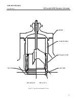
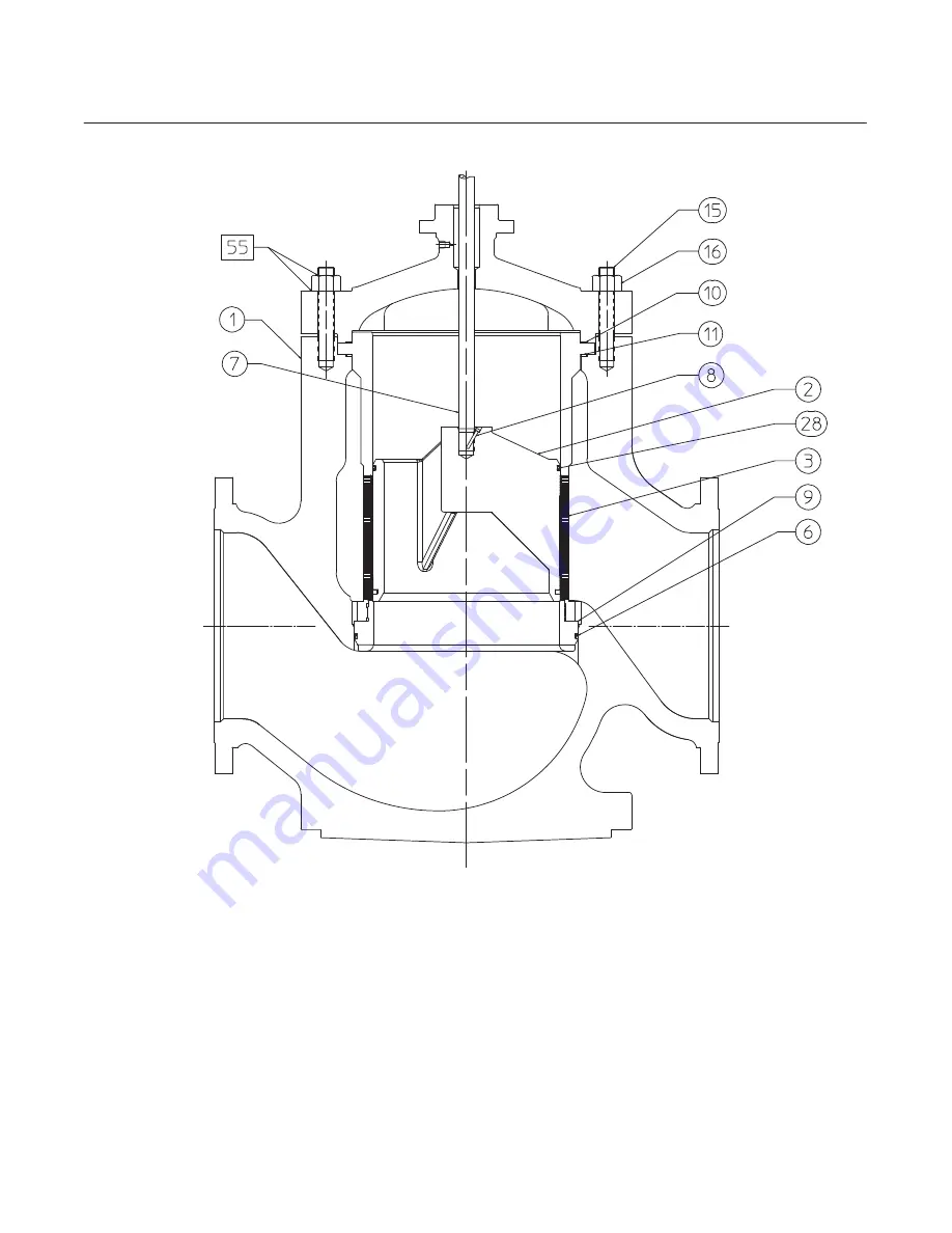
Figure 7. Typical Fisher EUT-2 or EWT-2 Valve
For EUD and EWD valves (figure 8) and EUT and
EWT valves (figure 9)
, install the seat ring gasket
(key 13).
Temporarily install screws or bolts into the tapped
holes in the seat ring (key 9), making sure the
seating surface is facing up. Lower the seat ring into
the valve body. Remove the temporary screws or
bolts.
Secure the seat ring (key 9) with the cap screws
(key 49). Tighten the cap screws in a criss-cross
pattern to a torque of 39 N
S
m (29 lbf
S
ft) for NPS 12
and 16 x 12 valves and to 92 N
S
m (68 lbf
S
ft) for NPS
16 through 24 x 20 valves.
2. Install a cage gasket (key 11) into the valve.
Temporarily install screws or bolts into the tapped
holes in the top of the cage assembly (key 3) to help
while installing this piece into the valve. Any
rotational orientation of the cage or assembly with
respect to the valve is acceptable.


